Socomec DIRIS A-40
Multifunction meter
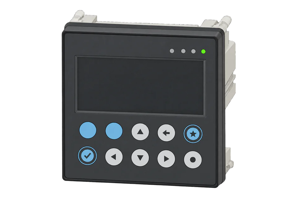
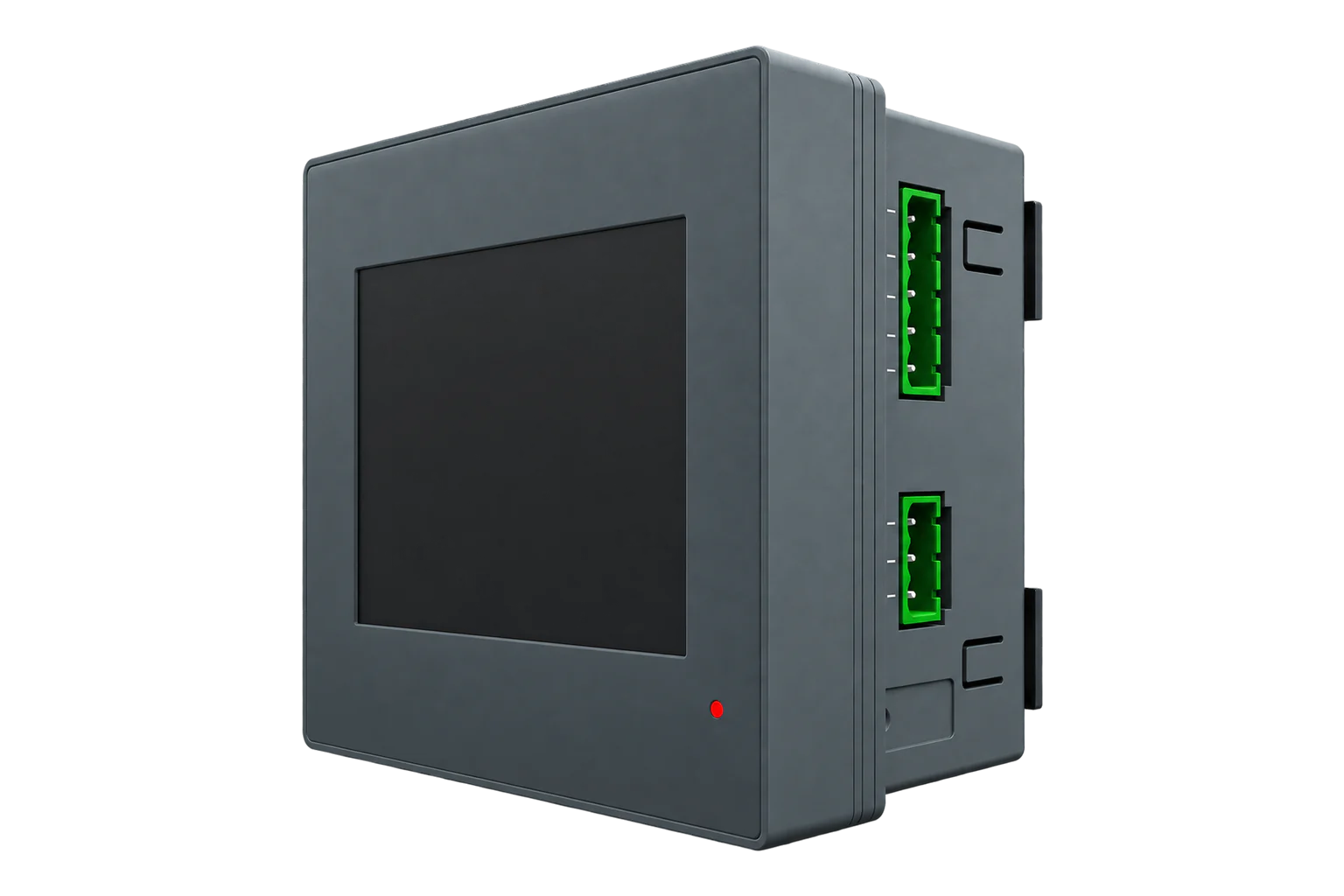
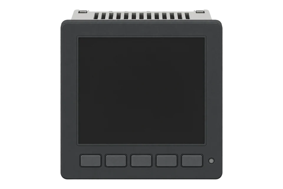
A 96 × 96 mm panel meter with a touchscreen that measures energy, power and power quality through Socomec's own plug-in current sensors, which it recognises by type and rating. Every version has Modbus RTU on RS-485; one adds Ethernet with Modbus TCP.
Compatibility
Compatible with EpiSensor Edge over Modbus RTU and Modbus TCP.
Connect its RS-485 port to a Modbus Interface or to a serial interface on the Gateway, or use its Ethernet port for Modbus TCP. Edge polls it with its Modbus client.
Edge reads 32 values from it, listed under Interface.
Connect it with
-
Modbus Interface ZMB-3XFrom €399 ex VAT Configure Modbus Interface
-
Gateway ZGW-20From €899 ex VAT Configure Gateway
-
Evaluation Gateway on a Raspberry Pi Edge with one device licensedFree Set up Evaluation Gateway on a Raspberry Pi


Specifications
The DIRIS A-40 is Socomec's panel-mounted multifunction meter, a performance measuring and monitoring device to IEC 61557-12 in a 96 × 96 mm format. It measures single-phase and three-phase networks, with or without neutral, from 50 to 300 V phase to neutral, and higher voltages through voltage transformers. It has three digital inputs and two outputs.1
- Power
- Mains. Auxiliary supply of 110 to 277 V AC phase to neutral, 277 to 400 V AC phase to phase, or 120 to 300 V DC, at 50 or 60 Hz. The Modbus version draws 4 VA at 110 to 277 V AC; the Ethernet and Profibus versions 6 VA.1
- Active energy and power accuracy
- Class 0.5 with TE, iTR or TF sensors; Class 1 with TR sensors; Class 0.2 for the meter alone (IEC 61557-12)1
- Reactive energy accuracy
- Class 21
- Voltage inputs
- 50 to 300 V AC L-N, 87 to 520 V AC L-L, CAT III; VT primary up to 400,000 V1
- Current inputs
- 3, for Socomec TE, TR, iTR and TF sensors; 1 A or 5 A transformers through an adapter1
- Power quality
- Harmonics to the 63rd, THD, TDD, unbalance, K-factor, EN 50160 dips, swells and interruptions1
- Inputs and outputs
- 3 optocoupler inputs, 2 optocoupler outputs (30 V DC, 20 mA)1
- References
- 4825 0500 (Modbus), 4825 0501 (Modbus and Ethernet), 4825 0502 (Modbus and Profibus)1
- Protection
- IP52 front, IP20 rear1
- Operating temperature
- -10 to 70 °C1
- Weight
- 326 g (4825 0500) to 349 g (4825 0502)1
Where it is used
Incomers and feeders in low-voltage switchboards, with split-core sensors where the cables cannot be disconnected.
Transformer and distribution board monitoringPower quality and harmonics on circuits feeding IT, UPS and drive loads.
Data centre power monitoring and PUE inputsBringing Socomec meters on an RS-485 bus or the site network into a BMS or SCADA system through Edge.
Modbus meter integration for a BMS or SCADA system
Interface
This register map is for the DIRIS A-40.
Communication settings
- RS-485
- Modbus RTU on 2 or 3 half-duplex wires, on every reference
- Baud rate
- 9600 to 115200 bit/s
- Serial settings
- Baud rate, parity, stop bits and address, set on the screen or with Easy Config
- Bus
- Up to 32 devices and 1,200 m per segment, 120 Ω at both ends
- Cable
- LiYCY shielded twisted pair
- Ethernet (4825 0501)
- Modbus TCP on port 502, Modbus RTU over TCP on port 503, and BACnet
- Web server (4825 0501)
- Default IP address 192.168.0.4
- Profibus (4825 0502)
- Profibus DP-V1 on a Sub-D9 connector
- USB
- Modbus RTU on micro USB, for configuration
- Read with
- FC03 (holding registers)
- Word order
- High word first on each 32-bit value
- Addresses
- Zero-based PDU addresses, as sent on the bus
From DIRIS A-40 installation and operating manual (545802B)1 and MODBUS tables of DIRIS A-40, v1.7.42.
Register map
| Point | Address | Hex | Format | Scale | Unit |
|---|---|---|---|---|---|
| Frequency | 18442 | 0x480A |
UINT32 | ×0.001 | Hz |
| Voltage L1-N | 18444 | 0x480C |
UINT32 | ×0.01 | V |
| Voltage L2-N | 18446 | 0x480E |
UINT32 | ×0.01 | V |
| Voltage L3-N | 18448 | 0x4810 |
UINT32 | ×0.01 | V |
| Voltage L1-L2 | 18452 | 0x4814 |
UINT32 | ×0.01 | V |
| Voltage L2-L3 | 18454 | 0x4816 |
UINT32 | ×0.01 | V |
| Voltage L3-L1 | 18456 | 0x4818 |
UINT32 | ×0.01 | V |
| Current L1 | 18458 | 0x481A |
UINT32 | ×0.001 | A |
| Current L2 | 18460 | 0x481C |
UINT32 | ×0.001 | A |
| Current L3 | 18462 | 0x481E |
UINT32 | ×0.001 | A |
| Neutral Current | 18464 | 0x4820 |
UINT32 | ×0.001 | A |
| Total Active Power | 18476 | 0x482C |
INT32 | ×1 | W |
| Total Reactive Power | 18478 | 0x482E |
INT32 | ×1 | var |
| Total Apparent Power | 18484 | 0x4834 |
UINT32 | ×1 | VA |
| Total Power Factor | 18486 | 0x4836 |
INT16 | ×0.001 | - |
| Active Power L1 | 18488 | 0x4838 |
INT32 | ×1 | W |
| Active Power L2 | 18490 | 0x483A |
INT32 | ×1 | W |
| Active Power L3 | 18492 | 0x483C |
INT32 | ×1 | W |
| Reactive Power L1 | 18494 | 0x483E |
INT32 | ×1 | var |
| Reactive Power L2 | 18496 | 0x4840 |
INT32 | ×1 | var |
| Reactive Power L3 | 18498 | 0x4842 |
INT32 | ×1 | var |
| Apparent Power L1 | 18512 | 0x4850 |
UINT32 | ×1 | VA |
| Apparent Power L2 | 18514 | 0x4852 |
UINT32 | ×1 | VA |
| Apparent Power L3 | 18516 | 0x4854 |
UINT32 | ×1 | VA |
| Power Factor L1 | 18518 | 0x4856 |
INT16 | ×0.001 | - |
| Power Factor L2 | 18519 | 0x4857 |
INT16 | ×0.001 | - |
| Power Factor L3 | 18520 | 0x4858 |
INT16 | ×0.001 | - |
| Import Active Energy | 19843 | 0x4D83 |
UINT32 | ×1 | kWh |
| Export Active Energy | 19846 | 0x4D86 |
UINT32 | ×1 | kWh |
| Import Reactive Energy | 19849 | 0x4D89 |
UINT32 | ×1 | kvarh |
| Export Reactive Energy | 19852 | 0x4D8C |
UINT32 | ×1 | kvarh |
| Total Apparent Energy | 19855 | 0x4D8F |
UINT32 | ×1 | kVAh |
Socomec lists every address in decimal and hexadecimal. The decimal address is the one sent on the bus: total active power is 18476 (0x482C).2
Scaling is in the table's units: voltage in 0.01 V, current in mA, frequency in mHz and power factor in thousandths. Each whole kWh counter has a residual register beside it in 0.1 Wh steps, which the map leaves out.2
This page covers references 4825 0500, 4825 0501 and 4825 0502. Check the reference on the label before you use the map on an older DIRIS A40 or A41.1
The communication table has distinct Network and Load blocks. The core map uses Load Inst., including V1 at 18444 (0x480C); the Network V1 address 36873 (0x9009) is a different entry, not an address-base conversion.2
Edge template
This JSON file supplies the register map. Applying it to an existing meter replaces its sensor list while retaining the site connection, unit ID and enable state.
| Model | Connection | Points | Version | Updated | Download |
|---|---|---|---|---|---|
| DIRIS A-40 | Modbus RTU over RS-485, Modbus TCP | 32 | 1.0.0 | Download |
Downloads need a signed-in account with Edge download access.
Use the template in Edge
- Import the JSON file
In Edge, open Settings, then Devices and Templates. Choose Import JSON and select the downloaded file. Confirm that the model and template name match your device.
- Load the map for your meter
For a new Modbus device, use Load Template before entering the manufacturer or model; it fills those fields and the register list. Set the name, site connection and unit ID, check the polling enable state, then test before saving. For an existing device, apply only to the matching model; this replaces its sensor list but retains its connection, unit ID and enable state.
- Test a reading
Use Test in the wizard and compare a known reading with the meter display. Check its unit, sign and scale, then confirm that timestamps keep advancing. These starter maps are read-only and leave exports off until you configure them.
Setup
-
Fit the current sensors
Plug a TE, TR, iTR or TF sensor into each current input with Socomec's RJ12 cable. The meter reads each sensor's type and rating, and raises a system alarm for a missing sensor, a current that does not match its voltage, or the wrong phase rotation.1
-
Wire the bus
Run LiYCY shielded twisted pair from the meter's RS-485 terminals to a ZMB-31 or the Gateway's serial interface. Keep to 32 devices and 1,200 m per segment and fit 120 Ω at both ends.1
-
Set the communication
Set the address, baud rate, parity and stop bits on the touchscreen or with Easy Config over the micro USB port, then set Edge to match. On 4825 0501, set DHCP or a fixed IP address for Modbus TCP on port 502.1
-
Prove the Load voltage decode
Read two registers with FC03 at literal address 18444 (0x480C). The Request PDU is 03 48 0C 00 02. A synthetic high-word-first payload 00 00 59 E4 is integer 23012, giving 230.12 V after multiplying by 0.01. Establish the returned word order against the simultaneous meter display; these example bytes are not a captured device response.2
-
Enable the map
Once voltage, current and total active power match the screen, enable the rest of the map and watch several fresh readings before you add exports or alarms.
Common questions
- Can the DIRIS A-40 use standard 5 A current transformers?
- Yes, through Socomec's 5 A adapter, up to 10000/5 A or 2000/1 A. The combined accuracy then depends on the transformer, because Socomec only states the chain accuracy for its own TE, TR, iTR and TF sensors.1
- Which address holds total active power?
- 18476 (0x482C), read with function code 3 as a signed 32-bit value in watts.2
- How are energy counters stored?
- Imported active energy starts at 19843: a uint32 whole-kWh value followed by a uint16 residual in 0.1 Wh steps. For example, 1234 whole kWh and residual 5678 mean 1234 + 5678 / 10000 = 1234.5678 kWh. The core template uses only the whole-kWh portion, so small interval changes can be invisible. Read the complete counter consistently if sub-kWh resolution is required.2
- Does this page also cover the older DIRIS A40 or A41?
- No. This page covers the touchscreen DIRIS A-40 references 4825 0500, 4825 0501 and 4825 0502 with communication table v1.7.4. An older DIRIS A40 or A41 needs its own matching documentation. The exact device label and firmware determine which register map to use.12
Related devices

Sources
- DIRIS A-40 installation and operating manual (545802B) (opens in a new tab) (PDF)
- MODBUS tables of DIRIS A-40, v1.7.4 (opens in a new tab)
- Socomec DIRIS A-40 register map (opens in a new tab)
Further reading
Product names and trademarks belong to their owners. Publication does not imply endorsement or a commercial relationship.