Veris Industries E30 and E31 BCPM
Multichannel energy meter
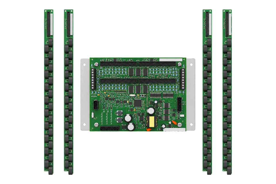
The E30 and E31 are branch circuit power meters (BCPM) from Veris Industries: one data acquisition board monitors up to 84 branch circuits plus two sets of four auxiliary inputs for the mains and neutral. The E30 uses current sensor strips of 21 solid-core sensors on 3/4 in or 1 in spacing, and the E31 uses split-core CTs on adapter boards for retrofit. Each comes as an Advanced (A), Intermediate (B) or Basic (C) board, which sets whether branch circuits report power and energy or current only. The board speaks Modbus RTU on RS-485 and answers at two Modbus addresses, one for each pair of strips. Veris's E3x point map numbers its registers from 1, gives most values both as 16-bit integers with their own scale registers and as 32-bit floats, and reports the board model in register 5.
Compatibility
Compatible with EpiSensor Edge over Modbus RTU
The E30 and E31 are compatible with EpiSensor Edge over Modbus RTU on the data acquisition board's RS-485 port, read through a ZMB-31 Modbus Interface or a Gateway serial port. Veris publishes the E3x point map with integer and float registers, scale registers, word order, model validity and the supported commands.
E30 and E31 boards in models A, B and C, using the E3x point map Rev. A. The map numbers registers from 1, so register 2252 is sent as address 2251. Site check: read the Device ID at register 5 at both Modbus addresses, then compare one branch current with a clamp meter. Read-only monitoring: no writes to the configuration, CT, breaker, alarm, reset or logical circuit registers.
Connect it with


For a panelboard where a wireless link avoids running a data cable back to the Gateway
- Modbus
- Wireless
- Edge
- Platforms
When the Gateway sits near the panelboards, or several boards share one wired RS-485 bus
- Modbus
- Edge
- Platforms
Models
| Models | Interface | Route into Edge |
|---|---|---|
| E30A and E31A (Advanced) | Current, power, power factor, demand and kWh for every branch circuit and the mains; voltage; Device ID 15172 | Read branch and mains values over Modbus RTU through a ZMB-31 or a Gateway serial port. |
| E30B and E31B (Intermediate) | Current and current demand for branch circuits; power, energy and voltage on the auxiliary (mains) inputs; Device ID 15171 | Same Modbus RTU route. Branch power and energy registers read as invalid, so read branch currents and the mains power and energy. |
| E30C and E31C (Basic) | Current only on all channels, with no voltage inputs; Device ID 15170 | Same Modbus RTU route for currents. No power or energy is available from a model C. |
| E30x042, E30x084 (sensor strips, option 0 for 3/4 in or 1 for 1 in spacing); E31x002, E31x004, E31x42, E31x84 (adapter boards and split-core CTs) | E30 kits with 2 or 4 strips of 21 solid-core 100 A sensors; E31 kits with 2 or 4 adapter boards, with or without 50 A split-core CTs | Same point map; a 4-strip or 4-adapter kit fills both Modbus addresses. |
Specifications
One E30 or E31 data acquisition board monitors 92 circuits: 84 branch circuits on four strips or adapter boards and two sets of auxiliary inputs for 3-phase mains and neutral, read through 0.333 V AC CTs. The E30 strips carry 21 solid-core 100 A sensors each, on 3/4 in (Square D) or 1 in (GE) spacing; the E31 adapter boards take up to 21 split-core CTs each for retrofit. A breaker size per channel and four user-configurable alarm thresholds can be set in the board, and an optional display shows local readings.123
- Models
- E30 + A, B or C board + CT option 0 (100 A, 3/4 in) or 1 (100 A, 1 in) + 42 (2 strips) or 84 (4 strips), for example E30A042. E31 + A, B or C board + 002 or 004 adapter boards without CTs, or 42 or 84 with 50 A CTs and ribbon cables. E31 CT six-packs: E31CT0 (50 A, 6 ft leads), E31CT0R20 (50 A, 20 ft) and E31CT2 (100 A, 4 ft).23
- Branch accuracy
- E30: current 1% of reading from 2 to 100 A and 2% from 0.25 to 2 A; power 3% of reading from 1 to 100%. E31: current 2% of reading from 2 to 100 A and 3% from 0.25 to 2 A; power 3% from 2 to 100 A and 4% from 0.25 to 2 A, at ±0.8 PF.23
- Mains accuracy
- Voltage 1% of reading from 90 to 277 V L-N; auxiliary power to IEC 61036 Class 1 and ANSI C12.1-2001; auxiliary current 2% of reading from 1 to 10% and 1% from 10 to 100% of CT rating (0.333 V AC).23
- Operation
- Input power 90 to 277 V AC, 50/60 Hz; sampling 2560 Hz; update about every 1.8 s for both panels; overload capability 10 kAIC; ribbon cables up to 20 ft (6 m).23
Interface
Documented measurements and integration boundaries for E30 and E31 BCPM.
- The map numbers registers from 1 and gives no zero-based column: register 1 is the serial number MSW and register 5 the Device ID. Read the numbers as one-based Modbus registers, so register 5 is sent as address 4 and register 2252 as 2251 (0x08CB). The Device ID read in the worked check proves the convention.
- Two Modbus addresses: the primary address is set on the main board's DIP switches and the secondary is always the primary plus 1. Each address carries the whole map for one pair of CT strips and one set of 4 auxiliary inputs.
- Supported commands: FC03 Read Holding Registers, FC06, FC16 and FC17 Report Slave ID, which returns a string such as "Veris Model Exxx Branch Circuit Monitor, S/N=0x12345678, Location=...". The map lists no FC04.
- Device ID at register 5: 15172 is model A (current and power on all channels plus voltage), 15171 model B (current on branch channels, power on the auxiliary channels, plus voltage) and 15170 model C (current only, no voltage). Channels a model does not support read 0x8000 in integer registers and 0x7FC00000 in floats.
- Integer registers are signed 16-bit values multiplied by 10 to the power held in their scale register: register 1336 (channel 1 current) with scale register 1000 at -1 gives the value times 0.1. A parameter with no scale register listed has scale 0. 32-bit integers such as kWh put the MSW in the lower register, and the energy scale applies to the whole 32-bit value.
- Floats are read-only 32-bit IEEE 754 values with the MSW in the lower register: 3.14159 is 0x40490FD0, MSW 0x4049 then LSW 0x0FD0. They need no scale register.
- Mains voltages, models A and B: frequency at 245 (float 600/601), L-N average 246 (602/603), L-L average 247 (604/605), A-N, B-N and C-N at 248 to 250 (floats 606, 608 and 610) and A-B, B-C and C-A at 251 to 253 (floats 612, 614 and 616), with voltage scale register 244.
- Auxiliary (mains) inputs 43 to 46: 3-phase kWh at 254/255 (float 618/619, energy scale 291); 3-phase total kW at 256 (float 620/621); 3-phase PF at 257 (float 622/623); kW phase 1 to 3 at 259 to 261 (floats 626 to 630); current phase 1 to 4 at 265 to 268 (floats 638 to 644), where phase 4 is neutral; present and maximum 3-phase kW demand at 277 and 278 (floats 662 and 664); 3-phase kVA at 540 (float 676).
- Branch circuits 1 to 42 in the 1PH map, with N the channel number: current at integer 1335 + N (float 2250 + 2N, scale register 999 + N) on all models; kW at integer 1251 + N (float 2082 + 2N, scale 1041 + N), PF at 1293 + N (float 2166 + 2N, fixed scale -3) and kWh at integer 1166 + 2N and 1167 + 2N (float 1998 + 2N, energy scale 1083 + N) on model A.
- Diagnostics: Device Health at register 532 flags frequency out of range, voltage clipping per phase, current clipping and a strip connection error; register 531 counts power-ups. The board updates its values about every 1.8 s.
- Writable registers: configuration 6 (feed and numbering layout, which also clears logical circuits when changed), location string 7 to 70, demand set-up 71 and 72, CT sizes 73 to 118, breaker sizes and alarm thresholds from 119, per-channel resets 1126 to 1167, AUX reset 294, global reset 295 (12345 resets the device), the real-time clock 554 to 557 and logical circuit assignment from 62068. Keep all of them out of a monitoring poll.
Assessment
E30 and E31 boards in models A, B and C, using the E3x point map Rev. A. The map numbers registers from 1, so register 2252 is sent as address 2251. Site check: read the Device ID at register 5 at both Modbus addresses, then compare one branch current with a clamp meter. Read-only monitoring: no writes to the configuration, CT, breaker, alarm, reset or logical circuit registers.
- InteroperabilitySupported with conditions
- Veris documents Modbus RTU with the supported commands, integer and float registers, scale registers, word order and model validity, and the Device ID register identifies the model. The map is one-based without a zero-based column, each board uses two Modbus addresses, and the map lists 8177 registers across its circuit layouts.12
- AccuracySupported with conditions
- Mains power to IEC 61036 Class 1 and ANSI C12.1-2001, and per-circuit current, power and energy on model A from 0.25 to 100 A. Branch power accuracy is 3 to 4% of reading, suited to load management and cost allocation rather than revenue billing, and models B and C report no branch power.123
- SecurityLimited
- The point map has no Modbus password for configuration or resets; the firmware download block's password register always reads 0. Modbus RTU has no encryption or authentication. Keep the bus private and the client read-only.1
- ReliabilitySupported with conditions
- Device Health at register 532 reports frequency, voltage and current clipping and strip connection errors, a power-up counter sits at 531, and energy and maximum values are non-volatile. The 2008 datasheets give no immunity test levels.12
- RuggednessSupported with conditions
- Rated 0 to 60 °C and below 95% RH non-condensing with 10 kAIC overload capability. The board, strips and adapter boards mount inside the panelboard.23
Setup
Read the Device ID at register 5, then channel 1 current at register 2252
The E3x point map Rev. A lists the Device ID at register 5 (15170, 15171 or 15172 for models C, B and A), Volts A-N as a float at registers 606/607, channel 1 current as an integer at register 1336 with scale register 1000 and as a float at 2252/2253, and channel 1 kWh as a float at 2000/2001 on model A. The map numbers registers from 1, so each request below sends the register number minus one.
- Request
- 01 03 00 04 00 01 C5 CB: Modbus address 1, FC03, address 0x0004 for register 5, one register, RTU CRC.
- Address convention
- Register 5 is sent as address 4, register 606 as 605 (0x025D), register 2252 as 2251 (0x08CB), register 1336 as 1335 (0x0537) and register 1000 as 999 (0x03E7). A request to address 5 reads register 6, the configuration register, which holds 0 to 3, so a Device ID of 15170 to 15172 confirms the convention.
- Synthetic response
- 01 03 02 3B 44 AB 47: two data bytes, 0x3B44 = 15172, so the board is model A with current and power on every channel.
- Voltage read
- 01 03 02 5D 00 02 54 61 reads Volts A-N from 0x025D. Synthetic response 01 03 04 43 8A A6 66 35 D7: MSW 0x438A first, then 0xA666, so the float is 0x438AA666 = 277.3 V.
- Current read
- 01 03 08 CB 00 02 B7 95 reads channel 1 current from 0x08CB. Synthetic response 01 03 04 41 48 00 00 6E 19 gives the float 0x41480000 = 12.5 A. The integer path agrees: 01 03 03 E7 00 01 34 79 reads scale register 1000, synthetic response 01 03 02 FF FF B9 F4 gives -1; then 01 03 05 37 00 01 35 08 reads register 1336, synthetic response 01 03 02 00 7D 78 65 gives 125, and 125 × 10^-1 = 12.5 A.
- Energy read
- 01 03 07 CF 00 02 F5 40 reads channel 1 kWh from 0x07CF (register 2000). Synthetic response 01 03 04 45 3C DB 33 35 D6 gives the float 0x453CDB33 = 3021.7 kWh.
- Acceptance
- Keep the points when the Device ID reads 15170, 15171 or 15172 at both addresses and channel 1 current agrees with a clamp meter at the same time. A model B or C returns 0x7FC00000 for branch power and energy, which is expected.
Acceptance: The response bytes are a synthetic decoder check, not a captured board reply. A real reply must give a valid Device ID and a branch current that agrees with a clamp meter before power and energy points are enabled.
-
Identify the board and kit
Read the model number on the board: A, B or C sets which values exist, and the kit code gives the number of strips or adapter boards. A kit with four strips or adapter boards uses both of the board's Modbus addresses.
-
Set the address and serial settings
Set the DIP switches for 2-wire RS-485, the Modbus address (the secondary address is this address plus 1), the baud rate (9600, 19200 or 38400) and parity. Enter the same settings, with 8 data bits and 1 stop bit, in the Edge serial client or the ZMB-31.
-
Wire the RS-485 pair
Wire the pair and shield to the 2-wire terminals of the 5-position connector and daisy-chain further boards on the same pair.
-
Read the Device ID at both addresses
Send FC03 for one register at address 4, register 5, at the primary and the secondary Modbus address. Expect 15172 for model A, 15171 for model B or 15170 for model C.
-
Compare one branch current
Read channel 1 current as a float at register 2252 (address 2251) and compare it with a clamp meter on the same breaker, then check the mains voltage at register 606 against the panel voltage.
-
Add the circuits
Add branch currents for all models, and branch kW and kWh for model A, using the floats. Read the auxiliary inputs for the mains. Never write to the configuration, CT, breaker, alarm, reset or logical circuit registers.
Common questions
- Why does an E30 or E31 answer at two Modbus addresses?
- Each board serves two pairs of CT strips or adapter boards and two sets of auxiliary inputs. The primary address set on the DIP switches carries the first pair and the secondary address, always the primary plus 1, carries the second, each with the complete point map. Address boards in steps of two on a shared bus.12
- How do I know whether an E3x board reports branch power?
- Read the Device ID at register 5. 15172 is model A, with current and power on every channel; 15171 is model B, with branch current and power on the auxiliary inputs only; 15170 is model C, current only. Registers a model does not support return 0x8000 or 0x7FC00000.1
- How do I scale the E3x integer registers?
- Multiply each integer register by 10 to the power held in its scale register. Channel currents use scale registers 1000 to 1041, branch kW 1042 to 1083 and branch kWh 1084 to 1125, and power factor has a fixed scale of -3. The floats need no scaling, so read those where the client supports them.1
- Does the E3x map use zero-based or one-based registers?
- The map numbers registers from 1 and gives no zero-based column, so send the register number minus one: register 5 goes on the wire as address 4. A Device ID read proves it, because the register next to it holds the configuration value 0 to 3.1
Related devices
More from Veris Industries

Sources
- E3x Series Modbus Pointmap and BACnet Objects, Rev. A (16 April 2014), Excel workbook BCPM_ModbusMap with the General, Common, 1PH, 2PH, 3PH and logical circuit maps; attached to Schneider Electric FAQ FA212184, which notes that Veris refers to the BCPM as the E30/E31 (opens in a new tab)
- E30 Series Panelboard Monitoring System datasheet (2008), with specifications, network communications and ordering information (opens in a new tab) (PDF)
- E31 Series Split-Core Panelboard Monitoring System datasheet (2008), with specifications, network communications and ordering information (opens in a new tab) (PDF)
Further reading
Product names and trademarks belong to their owners. Publication does not imply endorsement or a commercial relationship.