Socomec DIRIS Digiware I-35 AC
Multi-circuit current measurement module
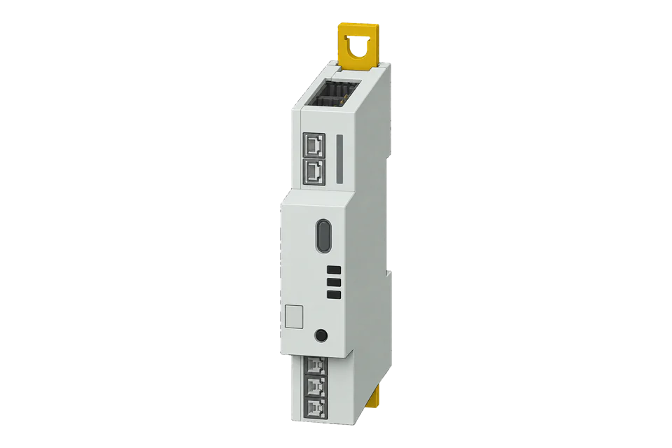
DIRIS Digiware I-35 AC is a three-input current acquisition module in a distributed metering system. It relies on compatible current sensors, shared voltage measurement and a communications gateway. Edge reaches the installed module through that gateway, while the configured load assignment determines which registers describe each circuit.
- Modbus TCP
Multi-circuit current measurement module
Compatibility
Compatible through Modbus TCP
The I-35 AC communication table defines Modbus registers, and the D-50/D-70 quick-start guide documents the Ethernet Modbus TCP gateway and downstream Digiware devices.
Exact I-35 AC reference 48290130, using communication table CMT 1.14.1 through a configured D-50 or D-70 gateway. I-35 MID and I-35 DC are distinct products. The module itself is not an Ethernet meter.
Connect it with
-
Gateway ZGW-20From €899 ex VAT Configure Gateway
-
Evaluation Gateway on a Raspberry Pi Edge with one device licensedFree Set up Evaluation Gateway on a Raspberry Pi

When the Digiware system has a commissioned Ethernet display/gateway
- Wired
- Edge
- Platforms
Models
| Models | Interface | Route into Edge |
|---|---|---|
| I-35 AC, 48290130 | Three current-sensor inputs; DIN-rail module on Digiware bus | Use the I-35 AC map and the configured load assignment. |
| D-50, 48290204 / D-70, 48290203 | Ethernet gateway with Modbus TCP; D-70 includes WEBVIEW-M | The gateway supplies network access to downstream Digiware devices. |
| I-35 MID / I-35 DC | Different certified or DC measurement variants | Use their exact product and communication documents instead of this AC map. |
Specifications
A Digiware installation separates voltage acquisition, current acquisition and network access. The I-35 contributes three sensor inputs; a U module supplies voltage measurements and a D gateway provides the illustrated Ethernet path. Map each input to its real circuit before comparing branch loads or aggregating energy.23
- Product reference
- 48290130, I-35 AC2
- Current inputs
- Three inputs for compatible Socomec current sensors2
- Module dimensions
- 18 × 90 × 65 mm; DIN-rail mounting; IP202
- Network endpoint
- D-50 or D-70, Ethernet 10/100; Modbus TCP3
- D gateway capacity
- Up to 32 displayed devices; serial limits depend on configured speed3
- Current format in worked check
- U32 in mA, high word first; 0xFFFFFFFF means unavailable1
- Read boundaries
- FC03 requests must remain inside the named communication table1
Interface
Documented measurements and integration boundaries for DIRIS Digiware I-35 AC.
- Load enable state and timestamp alongside instantaneous measurements.
- Current per input and configured load, in milliamps in the selected instantaneous table.
- Signed active power, reactive/apparent power and scaled power factor from their own typed fields.
- Import/export energy and demand tables where the configured load exposes them.
- Separate load blocks: the first load is not automatically a total for every connected circuit.
Assessment
Exact I-35 AC reference 48290130, using communication table CMT 1.14.1 through a configured D-50 or D-70 gateway. I-35 MID and I-35 DC are distinct products. The module itself is not an Ethernet meter.
- InteroperabilitySupported with conditions
- A published map provides functions, point types and unavailable values. Ethernet access depends on a separate commissioned D gateway.13
- AccuracyNot yet assessed
- The input and data formats are documented, but an accuracy class for the complete installed sensor, voltage-module and current-module chain has not been established in this review.12
- SecuritySupported with conditions
- The D gateway documents user roles and explicitly calls for default password changes. This does not establish encrypted Modbus transport; restrict the network endpoint.3
- ReliabilitySupported with conditions
- Load state, timestamps and typed unavailable values support detection of inactive or stale measurements; gateway diagnostics expose downstream communication faults.13
- RuggednessSupported with conditions
- The I-35 is an IP20 DIN-rail module and the D gateway is specified for indoor use. Enclosure and installation conditions apply to the whole assembly.23
Setup
Read load 1 current I1
The instantaneous load 1 table in CMT 1.14.1 defines current I1 at decimal 18458. This check does not change the module configuration.
- Target
- D gateway IP with the configured downstream I-35 AC device address
- Function
- FC03 Read Holding Registers
- PDU start
- 18458 decimal, 0x481A
- Length
- 2 registers
- Decode
- U32, high word first; mA converted to A with multiplier 0.001
- Independent vector
- A simulated 12.345 A is raw 12345 mA = 0x00003039, words 0x0000, 0x3039.
- Request PDU
- 03 48 1A 00 02; the TCP client supplies the transaction header and configured unit ID
- Unavailable
- 0xFFFFFFFF is reserved and must not become 4,294,967.295 A
Acceptance: Check the enabled state and freshness first, then compare with the same load and phase on the D display. This example validates the address and decoder definition; it is not a physical-device qualification.
-
Inventory the complete Digiware system
Record I-35 AC reference 48290130, its software version, current sensors, U voltage module and D-50/D-70 gateway. Confirm how each current input is assigned to a load and phase. A module with three inputs is not automatically three independent three-phase meters.
-
Confirm the downstream device address
Use the D gateway’s device list and diagnostics to identify the I-35 address and check that Digiware communication is healthy. Record the gateway IP and configured Modbus TCP endpoint. Preserve the installed addressing rather than running discovery changes on an operational system.
-
Read the load state first
Use CMT 1.14.1 as a best-effort starting point and compare the first readings with the D display. Load 1 status is FC03 address 18432, one register, low byte: 0 disabled, 1 enabled, 0xFF unavailable. Its timestamp at 18433 uses two registers, high word first, counting seconds since 1 January 2000. Reject 0xFFFFFFFF and check that it advances.
-
Verify one current measurement
Read FC03 at PDU address 18458 (0x481A), two registers, for load 1 current I1. Decode unsigned 32-bit, high word first, then convert mA to A with multiplier 0.001. Reject 0xFFFFFFFF as unavailable. Compare against the same load and phase on the D display.
-
Add other tables deliberately
Read load 1 active power at 18476 with FC03, two registers: PDU 03 48 2C 00 02. Decode S32, high word first, in W. Synthetic 0x00003039 is 12345 W; 0xFFFFCFC7 is -12345 W. Reject 0x7FFFFFFF. Frequency at 18442 is two-register U32 in mHz: 0x0000C350 becomes 50 Hz after multiplying by 0.001; reject 0xFFFFFFFF. Keep each request within its named table and compare the same configured load on the display. Load 2 and load 3 active power are at 20524 and 22572; do not sum them with load 1 unless the circuit assignments are distinct.
Common questions
- Can the I-35 connect directly to Ethernet?
- The I-35 is a Digiware current module. The illustrated network connection uses a D-50 or D-70 display/gateway with an Ethernet Modbus TCP service. Do not assign the D gateway’s hardware interfaces to the I-35 itself.3
- Why is current a thousand times too high?
- The selected load table reports U32 current in mA. Multiply by 0.001 to display A. Other fields use different units and factors; do not apply the current multiplier to power or energy.1
- Why does the decoder show a huge current?
- The current example uses U32 and reserves 0xFFFFFFFF. Active power uses S32 and reserves 0x7FFFFFFF; negative power remains a signed measurement. Check the enabled state and advancing timestamp before treating a reading as current.1
- Can I read across two tables in one request?
- The communication table forbids a request crossing table boundaries. Group points only inside a named table, even if nearby addresses look contiguous.1
Related devices
Sources
- DIRIS Digiware I-35 AC communication table, CMT 1.14.1 (opens in a new tab)
- DIRIS Digiware I-35 reference 48290130 (opens in a new tab)
- DIRIS Digiware D-50 / D-70 quick-start guide, 549829 (opens in a new tab) (PDF)
Further reading
Product names and trademarks belong to their owners. Publication does not imply endorsement or a commercial relationship.