Socomec COUNTIS E23 and E24
Power and energy meter
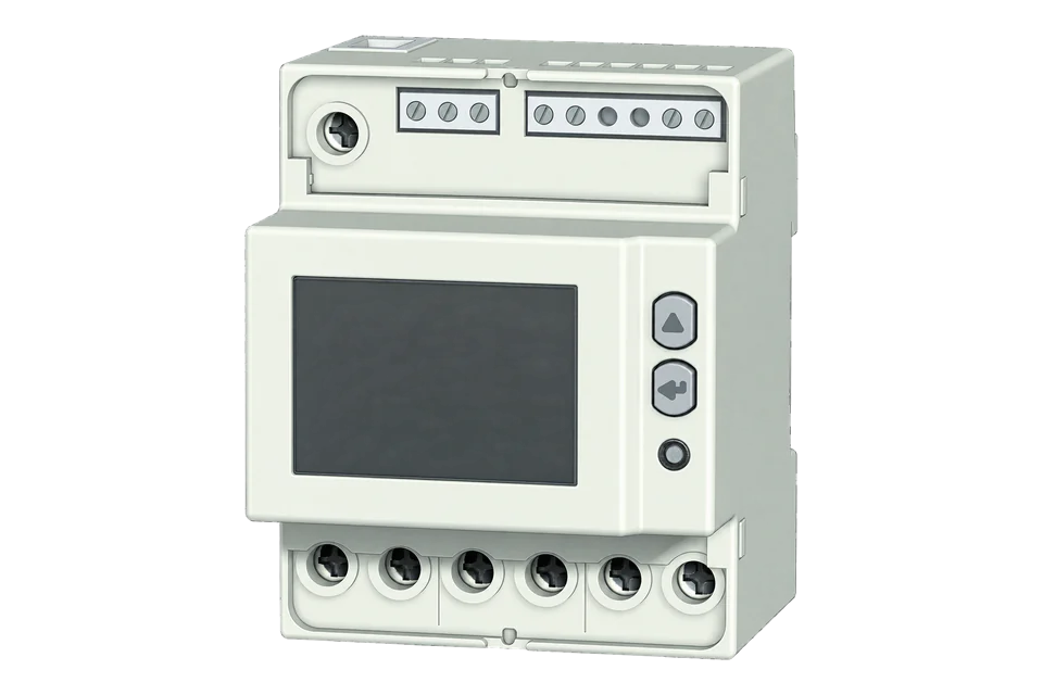
COUNTIS E23 and E24 measure three-phase circuits with neutral through a direct connection up to 80 A. Both provide RS-485 Modbus, energy totals and two tariffs in four DIN modules. E24 is the MID version; E23 is a separate model, not another name for the certified meter. Neither requires external current transformers.
- Modbus RTU
Power and energy meter
Compatibility
Documented Modbus RTU interface
The manual documents FC03 serial reads. Socomec’s public E23 table supplies a practical single-register frequency check. This is documented compatibility, without a physical Edge test.
E23 48503050 and E24 MID 48503051. Use the public E23 table V103.18 as a best-effort starting map, then compare with the display. For E24, confirm the same points respond before expanding. Read-only monitoring.
Connect it with
-
Modbus Interface ZMB-3XFrom €399 ex VAT Configure Modbus Interface
-
Gateway ZGW-20From €899 ex VAT Configure Gateway


For the exact serial meter identified below
- Modbus
- Wireless
- Edge
- Platforms
Models
| Models | Interface | Route into Edge |
|---|---|---|
| COUNTIS E23 / 48503050 | Direct 80 A, three-phase with neutral, RS-485 Modbus | Serial monitoring; this is not the MID model. |
| COUNTIS E24 / 48503051 | MID version of the direct meter; RS-485 Modbus | Same serial setup family, with specific sealing and metrological conditions. Remote RS-485 data is not itself the legally relevant indication. |
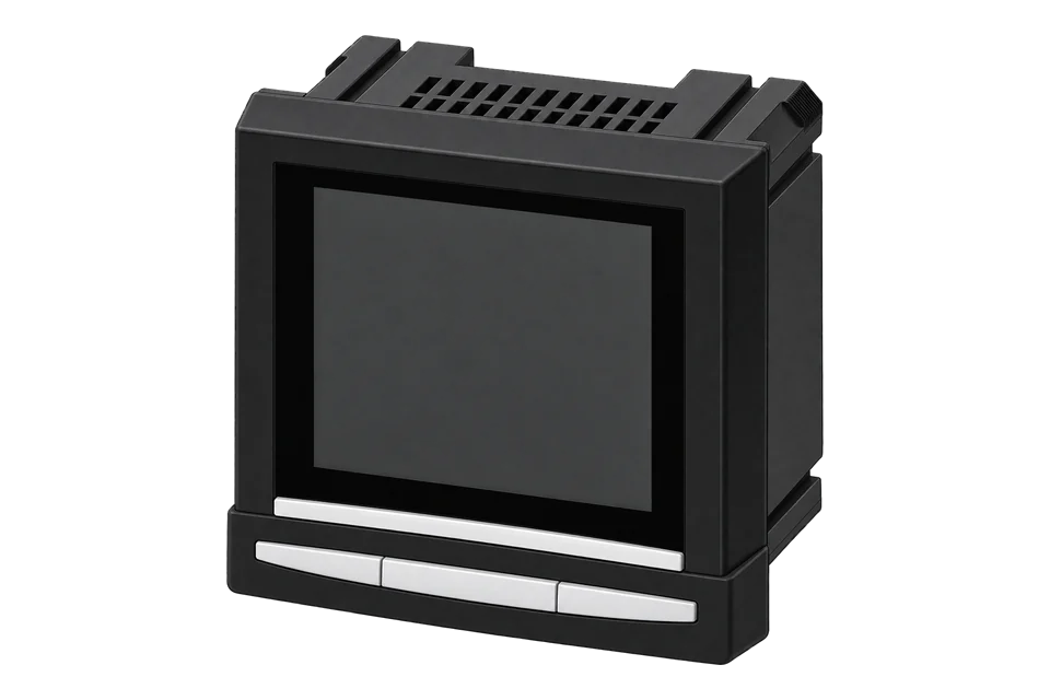
| COUNTIS E53 | Panel meter with external 5 A CT inputs in manual 536419B | A different electrical and communication-table family; not a substitute configuration for E23/E24. |
Specifications
Choose these meters for a direct three-phase circuit with neutral. The decision between E23 and E24 is metrological, while RS-485 settings determine how the monitoring system reaches the meter.1
- Exact references
- E23: 48503050. E24 MID: 48503051.1
- Input and network
- Direct connection up to 80 A per phase; three-phase with neutral. Reference current 5 A, not an external 5 A CT input.1
- Supply
- Self-powered from the measured network, 3 × 230/400 to 3 × 240/415 VAC, 50/60 Hz.1
- Tariffs
- Two tariffs. Choose communication or the voltage input as the tariff source; terminals 6–7 are not a dry-contact input.1
- RS-485
- Terminals 2 negative and 3 positive; terminal 1 is unconnected and may continue the shield. Modbus RTU, address 1–247.1
- Serial choices
- 1200–115200 bit/s in the documented menu; none, odd or even parity; one or two stop bits.1
- Mounting and enclosure
- Four DIN modules, 72 × 90 × 64 mm, inside an electrical cabinet; front IP51, case IP20.1
- Environment
- Operating −25 to +55 °C; humidity up to 80% within the manual’s installation conditions.1
- Accuracy
- Manual specifies class 1 active energy and class 2 reactive energy; E24 additionally carries class B/MID conditions.1
Interface
Documented measurements and integration boundaries for COUNTIS E23 and E24.
- Total and partial energy, with T1 and T2 tariff totals.
- Phase voltage and current, active/reactive/apparent power, power factor and frequency.
- Phase sequence and measurement direction support installation checks.
- Start with frequency; add voltage and current after checking the displayed values and scale.
Assessment
E23 48503050 and E24 MID 48503051. Use the public E23 table V103.18 as a best-effort starting map, then compare with the display. For E24, confirm the same points respond before expanding. Read-only monitoring.
- InteroperabilitySupported with conditions
- The documented serial interface and published electrical point rows support read-only monitoring with display checks.12
- AccuracySupported with conditions
- Direct 80 A three-phase-plus-neutral metering is defined; E24 adds specific MID conditions rather than legal status for remote data.1
- SecurityNot yet assessed
- The manual does not establish authenticated or encrypted access on this serial interface.1
- ReliabilitySupported with conditions
- FRAM retains energy and settings; display diagnostics identify phase and device problems. Treat failed reads as missing.1
- RuggednessSupported with conditions
- Cabinet mounting, ingress ratings and a defined temperature/humidity envelope are documented.1
- ScalabilitySupported with conditions
- Addressing, termination and a standard multidrop arrangement are documented; polling capacity depends on the actual bus.1
- LifecycleNot yet assessed
- The documentation does not establish current production, a minimum supported firmware or a future maintenance commitment.1
Setup
First read: frequency without word-order ambiguity
The E23 public table provides a one-register frequency point. Use it as the initial read and compare with the meter display.
- Function
- FC03, read holding registers
- Start address
- 51287 decimal (0xC857), raw table address. A client with one-based labels may show 51288.
- Length
- 1 register
- Decode
- Unsigned 16-bit integer ÷ 1000 = Hz
- Example
- 50000 (0xC350) ÷ 1000 = 50.0 Hz. Illustrative decode, not a measured response.
Acceptance: Keep the point when it agrees with the display. If it does not, check the address convention and installed model. Preserve the raw value and timestamps for troubleshooting.
-
Identify the meter and network
Record E23/48503050 or E24/48503051 and both firmware versions shown in the information menu. Confirm three-phase plus neutral and the direct connection current limit with the installer.
-
Check local readings first
Compare the display with the expected phase voltages, current direction and phase sequence. A missing-phase or reversed-sequence indication should be resolved before collecting energy totals.
-
Match SETUP 2 serial settings
Read the communication address, speed, parity and stop bits from SETUP 2 and enter the same settings in Edge. Do not use the partial-energy reset items merely to configure communications.
-
Follow the RS-485 terminal diagram
Use the manufacturer’s polarity labels, shield arrangement and line topology. Terminate the two bus ends as specified. The manual describes a standard 32-device, 1200 m arrangement; actual cable, loading and repeaters determine the installation.
-
Choose how tariffs are selected
SETUP 1 selects communication or the tariff input. The input uses 0 V for T1 and 80–276 VAC/DC for T2. Have the installer check that circuit; do not treat it as a low-voltage contact closure.
-
Start with the published frequency point
Read FC03 address 51287 as one unsigned 16-bit register and divide by 1000 for Hz. Compare with the display, then save the polling point. Record firmware and table revision with the configuration.
Common questions
- Does E24 make RS-485 energy data legally valid for billing?
- The manual explicitly excludes RS-485 information from legal metrological value. E24’s MID conditions include three-phase plus neutral, fitted and sealed terminal covers and a locked SET button. Use the metrologically relevant indication and applicable billing process.1
- Is the tariff input a dry contact?
- No. The wiring diagram assigns T1 at zero voltage and T2 at 80–276 VAC/DC. Communication can instead select tariffs when that source is chosen. The pulse output is a separate circuit on terminals 4–5.1
- Where should I start with the register table?
- Start with the single-register frequency example below. The public E23 table also lists phase-neutral voltage at 51284 to 51286 as U16 divided by 100 for volts. Compare each value with the display. Use the matching energy rows when adding totals.12
- Are these meters currently available to buy?
- The manufacturer retains documentation, but that does not establish present production or stock. Confirm the exact reference and support position with Socomec when specifying a new installation.1
Related devices

Sources
- COUNTIS E23/E24 installation and operating manual, 545877B (retained official reader extract) (opens in a new tab) (PDF)
- COUNTIS E23 public Modbus table V103.18: electrical measurement rows (opens in a new tab)
Further reading
Product names and trademarks belong to their owners. Publication does not imply endorsement or a commercial relationship.