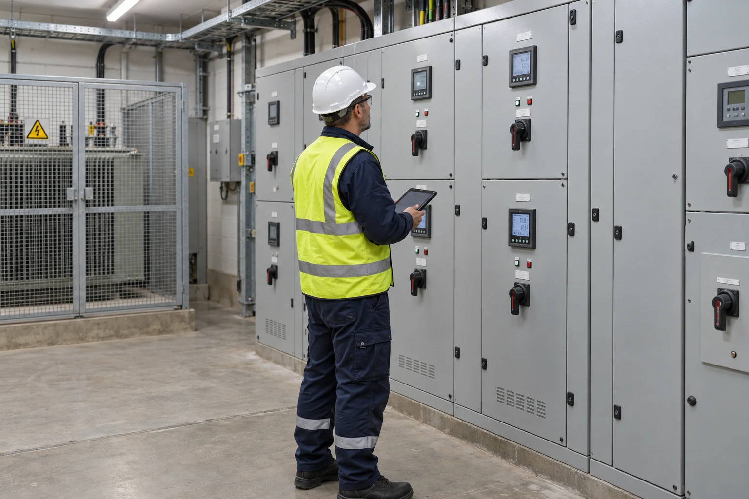
Transformer and distribution board monitoring
A meter at the incomer, meters on the feeders worth explaining, and a temperature probe where loading has to be read against heat.
- Measure
- Incomer active power, energy and per-phase current, then the feeders that carry the decision
- Scale
- Distribution board energy monitoring and branch circuit monitoring on one Gateway, up to 250 devices Gateway datasheet
- Sensors
- ZEM-65, 0.1 A to 3 kA, with ZEM-paired split-core CTs or Rogowski coils; the paired Rogowski options need no separate external integrator Wireless 3-Phase Electricity Monitor datasheet
- On site
- Interval demand and phase imbalance calculated where the meters are
How far down the board to go
Metering every way in a board costs more than it explains. Start at the incomer, add the feeders whose consumption changes a decision, and leave the rest until a question needs them.
| Incomer only | Incomer and selected feeders | |
|---|---|---|
| Answers | Total loading, demand and imbalance | Which loads drive the peak, and what changed |
| Reconciles | Against the supply meter | Feeders against the incomer, with the unmetered remainder named |
| Typical kit | One meter | One meter per feeder, on the same Gateway |
Hardware for a board or transformer measurement
One meter per measured point. The CT choice is set by the current and by what will physically fit around the conductor.

The incomer, and each feeder that has to be explained
1 per point three-phase, 3 or 4 wire
- Choose the CT rating and aperture: 120 A split-core at 14 mm, 300 A Rogowski, or 1 kA and 3 kA coils
Class 0.5S to IEC 62053-22 with its CTs, 0.1 A to 3 kA, CAT III at 480 V

Holds the hierarchy, the interval data and the alarms for the board
1 per site up to 250 wireless devices
If loading has to be read against temperature
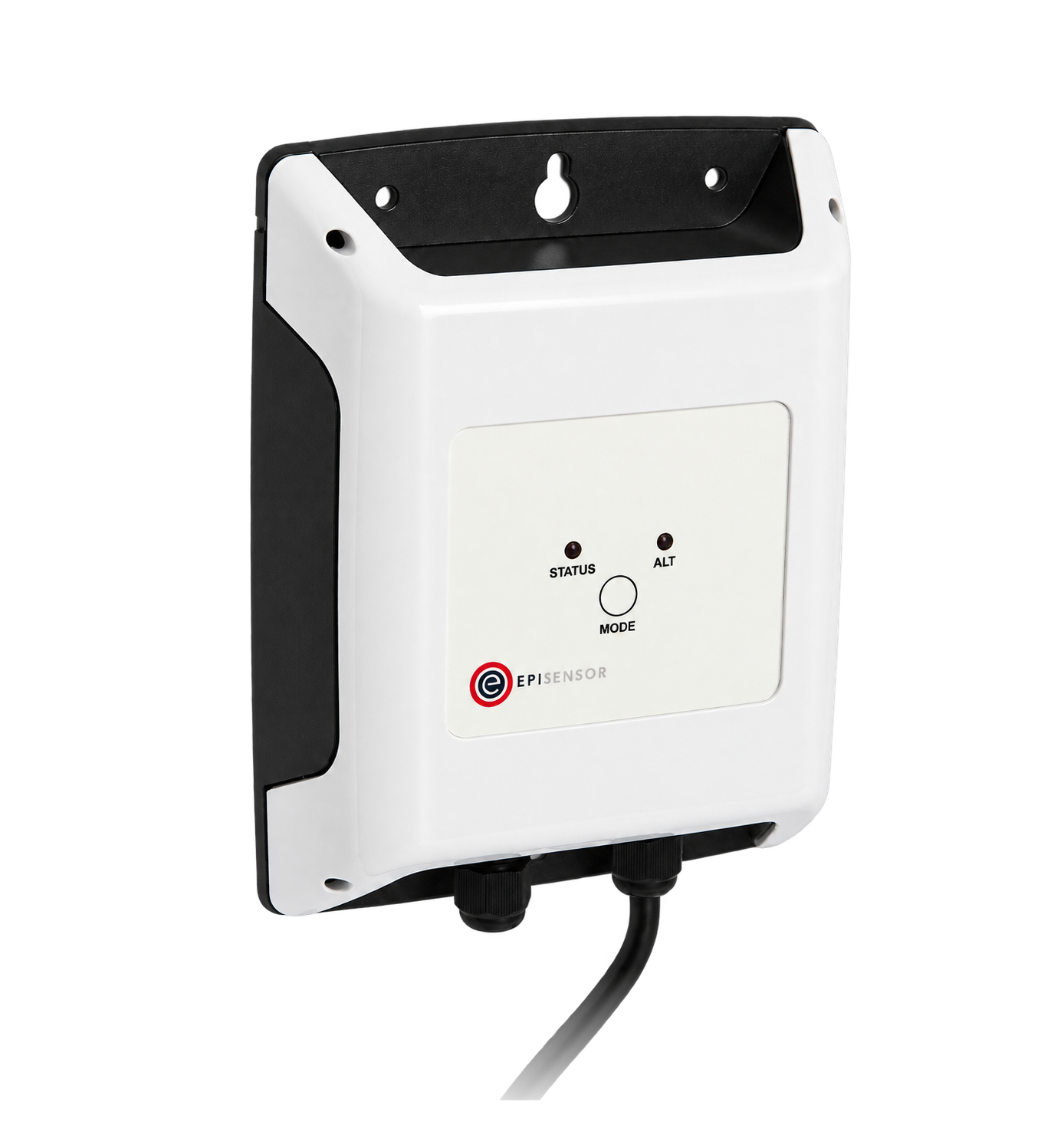
Enclosure, room or transformer surface temperature beside the electrical loading
1 per point steel probe, 2 m lead
±0.2 °C from 0 to 70 °C, ±0.5 °C to 105 °C
Where the meters go on the hierarchy
Draw the hierarchy first. Each meter's parent decides what its reading can be compared with.
From field measurement to Edge
Each field signal reaches its named EpiSensor interface, reports through the site Gateway and is handled locally in Edge.
- Wired
- Zigbee
- Edge
- Platforms
| Position | What it tells you | Reference | Sensor |
|---|---|---|---|
| Incomer | Total active power, energy, demand and per-phase current for the board | State whether the measurement is on the primary or the secondary side, and use the matching voltage reference | ZEM-65 (on this page), incomer |
| Material feeders | Which loads drive the peak, and how they move against it | Chosen by consequence: a spare way with no load explains nothing | ZEM-65 (on this page), one per feeder |
| Per-phase detail | Imbalance that a three-phase total hides | Keep the per-phase currents; neutral current cannot be inferred from active power | ZEM-65 (on this page) |
| Enclosure temperature | How hot the panel or transformer room runs while it is loaded | Equipment limits come from the equipment, not from a general room threshold Probe Temperature Sensor datasheet | TES-21 (on this page) |
Check more than the current rating. The aperture selector checks maximum current and the reviewed clear opening only. Output type, burden, accuracy class, insulation and installation category remain separate checks.
The ZEM accepts its paired Rogowski coils directly. The EpiSensor-supplied Rogowski options are paired with the ZEM input and need no separate external integrator. Do not generalise that pairing to an arbitrary Rogowski coil.
Leave work inside the board to a qualified electrician. Fitting CTs and voltage references is electrical work. Isolation, CT shorting and phase association are the electrician's, not the monitoring plan's.
Loading, demand and imbalance in Edge
The hierarchy lives on the Gateway, so the comparisons happen where the meters are.
- Parent against children
- A calculated sensor subtracts the metered feeders from the incomer, so the unmetered remainder is a value with a name.
- Demand, not just energy
- Interval demand is calculated from the same readings, on the interval the supply contract uses.
- Imbalance is watched, not derived
- Per-phase currents are kept as their own points, and a limit rule can compare them.
- A rising panel temperature
- A limit rule on the probe raises an alarm when the enclosure runs hotter than the equipment's own limit.
Commissioning checks
A competent person does the electrical work; these are the checks on what it produced.
-
Phase and polarity are confirmed
With a known load running, compare each phase's current and the power direction against an independent instrument.
Pass when every phase matches its label, and no channel reads negative when it should be importing.
-
CT ratios are recorded
Write down the CT type, ratio, aperture and the conductor each one is fitted to, with a photograph.
Pass when the record would let somebody else replace a CT correctly.
-
The board reconciles
Compare the incomer with the sum of the measured feeders over one complete interval.
Pass when the difference is stable and matches the loads known to be unmetered.
-
A load step moves parent and child
Switch a significant load and watch the feeder and the incomer.
Pass when both change together, by about the same amount, in the same interval.
-
The temperature point is where it says
Photograph the probe's position and compare its reading with a handheld instrument at the same surface.
Pass when the two agree, and the position is on the drawing.
Limits of this measurement
A meter reports what a circuit did. It decides nothing about what the circuit is allowed to do.
- Monitoring does not establish transformer capacity, conductor ampacity, protection coordination, fault duty or code compliance.
- A CT is chosen on aperture, output, burden, accuracy and installation category, not on a current rating alone.
- A temperature reading means nothing without the equipment's own limit and a stated measurement position.
- Electrical work stays with the qualified person who did it, including isolation and CT safety.
Sources
- IEC 61869 instrument transformers (opens in a new tab) (opens in a new tab) IEC
- Wireless 3-Phase Electricity Monitor datasheet (opens in a new tab) EpiSensor. Specifications, ranges and ordering codes.
Related
-
Tenant submetering and cost allocation
Meter each tenancy, the landlord supply and common services, and export a dated record that reconciles with the main meter. -
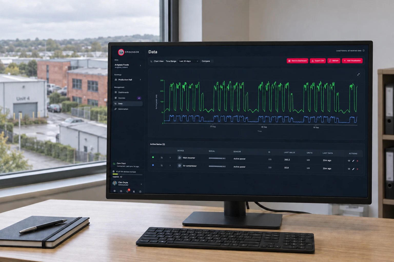
Multi-site energy monitoring
A Gateway on every site supports remote energy monitoring with local data continuity, a consistent point register and named owners for connections, credentials and change.
- OverviewEnergy monitoring
- CalculatorCurrent transformer selection
- CalculatorTransformer current calculator
- GuideSelecting current transformers (CTs) for energy monitoring
- GuideConductor size, voltage drop and CT aperture
Third-party devices for this application
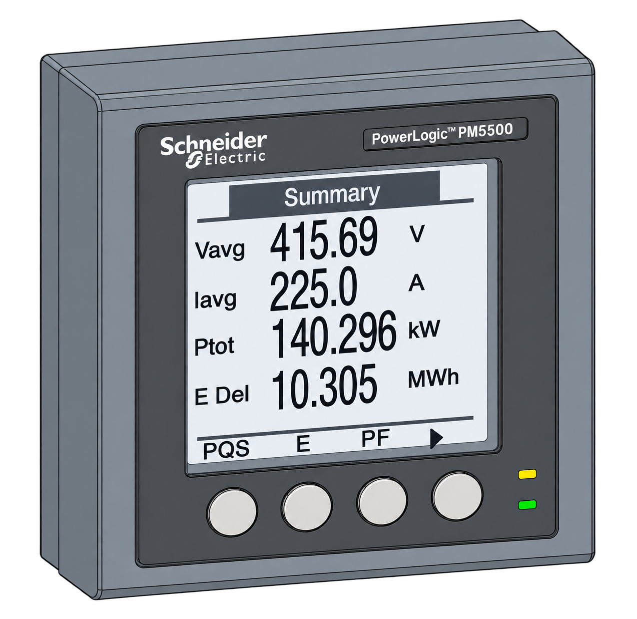



More in the Device Directory: Energy meters (62), Current transformers (7), Temperature and humidity sensors (21)
Choose the CTs that will actually fit your board
An engineer can choose the CTs that fit, say which feeders are worth metering, and size the Gateway.