Socomec COUNTIS E53
Power and energy meter
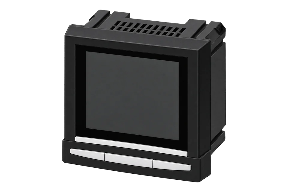
COUNTIS E53 is a panel meter for external current transformers, with RS-485 JBUS/Modbus RTU and four tariffs controlled through communications. This guide concerns reference 48503011 as documented by manual 536419B. It is useful when connecting an existing switchboard meter: the CT secondary, auxiliary supply and communication table matter more than the wider COUNTIS family name.
- Modbus RTU
Power and energy meter
Compatibility
Documented Modbus RTU interface
The documented RS-485 Modbus RTU interface connects through an isolated serial interface. The public V0.61 table supplies starting points for identification and electrical measurements.
Reference 48503011 retains the 5 A CT-secondary rating in manual 536419B. Use the public combined table as a best-effort starting map, compare the decoded values with the meter display and retain successful read settings. Keep monitoring read-only; tariff changes, resets and CT configuration belong to the installer. No prepared import or physical Edge test is included.
Connect it with
-
Modbus Interface ZMB-3XFrom €399 ex VAT Configure Modbus Interface
-
Gateway ZGW-20From €899 ex VAT Configure Gateway


For the exact serial meter identified below
- Modbus
- Wireless
- Edge
- Platforms
Models
| Models | Interface | Route into Edge |
|---|---|---|
| COUNTIS E53 / 48503011 | 5 A CT-secondary input, separate auxiliary supply, RS-485 RTU | Serial monitoring after the exact installed communication table is qualified. |
| COUNTIS E50 | Pulse-output model in the same installation manual | Do not infer an E53 RS-485 port from the shared manual title. |
| COUNTIS E50R and E53R | Separate variants named by a later combined communication table | Not covered by this exact E53 electrical and firmware scope. |
| COUNTIS E23 and E24 | Direct 80 A DIN meters | Different current inputs, mounting and communication-table generation. |
Specifications
The retained manual defines a 5 A CT secondary, not a generic 1 A/5 A selectable input. It also separates the auxiliary supply from the voltage measurement circuit, which matters when replacing or reconnecting an installed panel meter.1
- Exact scope
- COUNTIS E53, reference 48503011; manual 536419B.1
- Current input
- External CTs with 5 A secondary; configured primary up to 9999 A in this manual. Permanent secondary overload 6 A is not a rated operating target.1
- Voltage measurement
- Direct voltage measurement: 50–520 VAC phase-to-phase or 28–300 VAC phase-to-neutral.1
- Auxiliary supply
- 110–400 VAC, 50/60 Hz ±10%; or 120–350 VDC ±20%; consumption below 10 VA.1
- Networks
- Three-phase three- or four-wire, two-phase two-wire and single-phase systems, using the appropriate manufacturer diagram.1
- Communication
- RS-485 two- or three-wire half-duplex, JBUS/Modbus RTU; 2400–38400 bit/s.1
- Mounting
- Panel case 97 × 97 × 60 mm; depth 80 mm with all optional modules. Front IP52, case IP20.1
- Accuracy
- Manual specifies IEC 62053-22 class 0.5S active energy and IEC 62053-23 class 2 reactive energy; the external CT contributes additional measurement error.1
- Environment
- Operating −10 to +55 °C, within the manual’s installation conditions.1
Interface
Documented measurements and integration boundaries for COUNTIS E53.
- Total and partial active/reactive energy.
- Instantaneous active, reactive and apparent power; phase voltage/current and four-quadrant power factor.
- Four tariffs managed through the communication interface.
- Public table candidates: version at 50006, phase-neutral voltage at 50520/50522/50524 (U32 × 0.01 V), phase current at 50528/50530/50532 (U32 mA) and imported active energy at 50770 (U32 kWh). Electrical values use two registers; version uses one.
Assessment
Reference 48503011 retains the 5 A CT-secondary rating in manual 536419B. Use the public combined table as a best-effort starting map, compare the decoded values with the meter display and retain successful read settings. Keep monitoring read-only; tariff changes, resets and CT configuration belong to the installer. No prepared import or physical Edge test is included.
- InteroperabilitySupported with conditions
- The local RTU interface and public table provide concrete read candidates. Initial display comparisons establish address convention, word order and scaling for the installed meter.12
- AccuracySupported with conditions
- Class 0.5S active-energy metering and a 5 A CT-secondary input are documented; CT selection and configuration affect system accuracy.1
- SecurityNot yet assessed
- No authenticated or encrypted serial transport is established by the retained manual.1
- ReliabilitySupported with conditions
- A local display and connection-test function support diagnosis independently of the remote system; remote invalid-value handling remains unconfirmed.1
- RuggednessSupported with conditions
- Panel/case ingress ratings and the operating temperature range are documented.1
- ScalabilitySupported with conditions
- A standard multidrop arrangement and repeater guidance are documented, subject to the actual cable and bus design.1
- LifecycleNot yet assessed
- The retained historical manual does not establish current production, supported firmware versions or future maintenance.1
Setup
-
Identify the installed hardware
Record E53 and reference 48503011, firmware and fitted options. Check the CT secondary against the 5 A input documented here. Do not borrow the electrical ratings of an R variant or a newer COUNTIS model.
-
Check network and transformer configuration
Have the authorised installer confirm the network diagram and CT primary setting. Compare phase currents, voltage and power factor on the display before configuring software. CT wiring work requires the manufacturer’s safe shorting and isolation procedure.
-
Verify the separate auxiliary supply
Check the installed auxiliary supply against the AC or DC range on the meter. A correct measurement-voltage circuit does not by itself establish that the meter has the correct auxiliary power.
-
Read the serial menu
Record Adr, baud rate, parity and stop bits. The manual provides 2400, 4800, 9600, 19200 and 38400 bit/s, none/even/odd parity and one/two stop bits. Match the installed choices in Edge rather than assume a default.
-
Use the documented line topology
The manual describes up to 31 meters over 1200 m in its standard RS-485 arrangement, with termination at both ends and repeaters for larger arrangements. A reference to TCP-IP alternatives does not mean this meter has a native Ethernet port.
-
Start with public register candidates
For the initial candidate read, try FC03 (read holding registers). Record the table version at 50006 (0xC356) and software version at 50007 (0xC357), each one U16. Then try phase-neutral voltage V1 at 50520 (0xC558), two-register U32 × 0.01 V. These are table addresses; a one-based client label may be one higher. Compare decoding with the display. The measurement block includes transformer scaling, so check before adding another CT multiplier. Save the read function and word order that give the matching value.
Common questions
- Can I use a 1 A CT secondary?
- The retained manual specifies 5 A secondary. This guide does not extend that rating to 1 A. Check the exact hardware documentation instead of applying a newer family’s input options.1
- Does the E53 have Ethernet?
- The documented interface is RS-485 RTU. The manual mentions other networking solutions, but does not establish a native Ethernet port on this E53. A serial-to-network interface is a separate component.1
- Where should I start with the register map?
- Use Socomec’s public combined table V0.61 for the identification and electrical candidates above. Begin with one value and the local display rather than import every row. Keep the older E53’s 5 A input rating; a later table’s selectable 1 A/5 A setting does not change that hardware. The E23 single-register frequency example belongs to another map and should not be copied here.12
- Is this a recommendation for a new installation?
- It is primarily a guide to an installed E53 documented by manual 536419B. Present production, stock and future support have not been established. Confirm those with Socomec before selecting this reference for new equipment.1
Related devices

Sources
- COUNTIS E50/E53 operating manual 536419B, English technical characteristics (retained official reader extract) (opens in a new tab) (PDF)
- COUNTIS E50/E53/E50R/E53R Modbus table V0.61, identification and measurement candidates (official reader extract) (opens in a new tab)
Further reading
Product names and trademarks belong to their owners. Publication does not imply endorsement or a commercial relationship.