Veris Industries E50C2 and E50C3
Power and energy meter
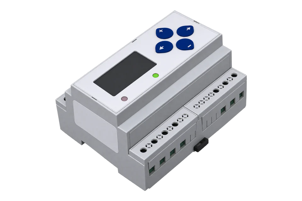
The E50 is a compact three-phase power and energy meter from Veris Industries for DIN rail or screw mounting in a panel; Schneider Electric's download centre hosts its current installation guide. It measures 90 V L-N to 600 V L-L systems through external CTs with 0.333 V or 1 V outputs, from 5 A to 32,000 A primary. The E50C2 adds an RS-485 port with Modbus RTU and the full data set, and the E50C3 adds a real-time clock and ten logging buffers on the same map. Veris numbers its registers from 001 and gives every quantity twice: as a 16-bit integer that must be scaled by a power-of-ten scale register, and as a 32-bit float from register 257 that needs no scaling. The E50B1 has pulse outputs only.
Compatibility
Compatible with EpiSensor Edge over Modbus RTU
The E50C2 and E50C3 are compatible with EpiSensor Edge over Modbus RTU on their 2-wire RS-485 port, read through a ZMB-31 Modbus Interface or a Gateway serial port. Veris publishes the point map with register numbers, formats, units, scale factors, word order and supported function codes in installation guide ZL0103-0D.
E50C2 and E50C3, using the point map in installation guide ZL0103-0D. The map numbers registers from 001, so register 257 is sent as address 256. Site check: read Voltage A-N as a float from register 293 and compare it with the display. Read-only monitoring: no writes to the command register 129 or the configuration registers.
Connect it with


For a meter in a panelboard where a wireless link avoids running a data cable back to the Gateway
- Modbus
- Wireless
- Edge
- Platforms
When the Gateway sits near the meters, or several E50 meters share one wired RS-485 bus
- Modbus
- Edge
- Platforms
Models
| Models | Interface | Route into Edge |
|---|---|---|
| E50C2 | RS-485 2-wire with Modbus RTU and the full data set (FDS); normally open real energy pulse contact and normally closed phase loss alarm contact | Read the RS-485 port with Modbus RTU through a ZMB-31 or a Gateway serial port. |
| E50C3 | As the E50C2, plus a real-time clock, configuration registers 155 to 178 and ten logging buffers read at registers 8000 to 13760 | Same Modbus RTU route and the same measurement registers. Edge reads the live values; leave the log read page register 158 at 0. |
| E50B1 | Pulse outputs only: a real energy pulse contact, a reactive energy pulse contact and the phase loss alarm, with no RS-485 port | No Modbus port. Use an E50C2 where Edge needs to read the meter. |
Specifications
- Models
- E50B1 pulse output only (2 pulses); E50C2 Modbus output, full data set; E50C3 Modbus output with data logging.1
- Voltage inputs
- 90 V L-N (156 V L-L) minimum for stated accuracy; UL maximum 600 V L-L (347 V L-N); CE maximum 300 V L-N; +20% over-range; 45 to 65 Hz. Single-phase 2-wire and 3-wire, three-phase delta and grounded wye.1
- Current inputs
- 0 to 0.333 V AC or 0 to 1.0 V AC CT inputs (+20% over-range), CT primary adjustable from 5 A to 32,000 A; for 1 V or 0.33 V current transducers only.12
- Accuracy
- Real power and energy IEC 62053-22 Class 0.2S and ANSI C12.20 0.2%; reactive power and energy IEC 62053-23 Class 2; current and voltage 0.4% (+0.015% per °C from 25 °C). The 2008 datasheet gave 0.5% for the first E50 models.12
- Sampling
- 2520 samples per second, data update every 1 s, true RMS to the 21st harmonic at 60 Hz.1
- Communication
- E50C2 and E50C3: RS-485 2-wire, Modbus RTU, 1200 to 38400 baud, parity none, even or odd, address 1 to 247; factory address 001, 19200 baud, no parity. RS-485 transceivers are ¼ unit load or less.1
- Data logging
- E50C3: real-time clock and 10 user-configurable buffers of 5760 16-bit entries each; at a 15-minute interval each buffer holds 60 days.1
- Outputs
- Normally closed phase loss alarm contact and normally open real energy pulse contact on all models, 30 V AC/DC and 100 mA maximum at 25 °C.1
- Control power
- AC: 5 VA maximum, 90 V minimum, UL maximum 600 V L-L (347 V L-N), CE maximum 300 V L-N. DC: 3 W maximum, 125 to 300 V DC with external current limiting. Ride-through 100 ms at 120 V AC.1
- Housing
- 0.28 kg; IP40 front display and IP20 meter; T35 DIN rail to EN 50022 or screw mounting; 24 to 14 AWG terminals.1
- Environment
- Operating -30 to 70 °C, storage -40 to 85 °C, below 95% RH non-condensing, up to 3000 m; indoor use only, pollution degree 2.1
- Approvals
- cULus to UL 508 (open type device) and CSA 22.2 No. 14-05; CE to IEC/EN 61010-1; CAT III; FCC part 15 Class B emissions; EN 61000 Class A immunity.1
Interface
Documented measurements and integration boundaries for E50C2 and E50C3.
- The map numbers registers from 001 and prints no zero-based column: integer data starts at 001, configuration at 129 and floats at 257, and the hex the guide prints beside them (257 is 0x101) is the same register number in hexadecimal. Read the numbers as one-based Modbus registers, so register 257 is sent as address 256 (0x0100). If the first float does not agree with the display, check the client's register base before changing anything else.
- The meter answers FC03 (read holding registers) and FC04 (read input registers), FC06 and FC16 for writes, FC17 (Report ID, returning "Veris Industries E50xx Power Meter Full Data Set") and FC43 Read Device Identification.
- Float registers are 32-bit IEEE 754 values with the upper 16 bits (MSR) in the lower-numbered register: register 257 holds the high word and 258 the low word. ULong energy counters use the same order.
- Float block, no scaling: real energy in kWh at 257/258; total real power in kW at 261/262; reactive power in kVAR at 263/264; apparent power in kVA at 265/266; total power factor at 267/268; average L-L and L-N voltage at 269/270 and 271/272; average current at 273/274.
- Per-phase floats: real power A, B and C at 275, 277 and 279 in kW; power factor at 281 to 285; voltage A-B, B-C and A-C at 287, 289 and 291; voltage A-N, B-N and C-N at 293, 295 and 297 in volts; current A, B and C at 299, 301 and 303 in amps; frequency (from phase A) at 307/308 in Hz.
- Energy and demand floats: apparent energy in kVAh at 309/310 and reactive energy in kVARh at 311/312; present demand in kW, kVAR and kVA at 325, 327 and 329; maximum demand at 331, 333 and 335. Per-phase real energy at 341, 343 and 345 needs firmware later than 1.018.
- Integer block, UInt unless stated: real energy (ULong, MSR at 001, LSR at 002) in kWh; total kW, kVAR and kVA at 003 to 005; total power factor at 006 in 0.0001; voltages at 007, 008 and 016 to 021; currents at 009 and 022 to 024; frequency at 026 in 0.01 Hz.
- Integer values in kW, kVAR, kVA, kWh, volts and amps must be scaled by the scale registers, which hold a signed power of ten from -4 to 4: 138 for current (I), 139 for voltage (V), 140 for power (W) and 141 for energy (E). The value is the register times 10 to that power, and the scale changes when the CT, PT or system type changes. The floats are not scaled.
- Values a system type does not support read QNAN: 0x8000 in integer registers and 0x7FC00000 in floats. Register 025 and the float at 305/306 are reserved and always read QNAN.
- Diagnostic Alert Bitmap at register 146: bits 0 to 5 flag voltage or current out of range on phases A to C, bit 6 frequency out of range, bits 8 to 10 phase loss, bits 11 to 13 low power factor below 0.5 from mis-wired phases, and bits 14 and 15 pulse output errors. Register 147 counts energy accumulator resets.
- Configuration registers: system type 130 (10, 11, 12, 31 or 40, with 40 for three-phase wye), CT primary 131, CT secondary 132 (1 or 1/3 V), PT ratio 133 (scaled by 100), system voltage 134 and demand sub-intervals 149 and 150. Read them to confirm the setup.
- Command register 129 clears energy (30078), restarts demand (21211), resets maximum demand (21212), resets the E50C3 log (16640) and clears pulse counters (16498). The display's SETUP and RESET passwords default to 00000, and the point map lists no Modbus password register, so keep 129 and every configuration register out of a monitoring poll.
Assessment
E50C2 and E50C3, using the point map in installation guide ZL0103-0D. The map numbers registers from 001, so register 257 is sent as address 256. Site check: read Voltage A-N as a float from register 293 and compare it with the display. Read-only monitoring: no writes to the command register 129 or the configuration registers.
- InteroperabilitySupported with conditions
- Veris documents Modbus RTU with the supported function codes, formats, units, scale factors and word order, and gives every quantity as a float. The map prints one-based register numbers without a zero-based column, and the guide does not state data bits or stop bits.1
- AccuracySupported with conditions
- Class 0.2S to IEC 62053-22 and ANSI C12.20 0.2% for real energy in installation guide ZL0103-0D, with per-phase power, per-phase real energy and demand values. The map has one real energy counter and no separate import and export registers, and accuracy also depends on the 0.333 V or 1 V CTs and the ratios set on the meter.12
- SecurityLimited
- SETUP and RESET passwords protect the display menus and default to 00000. The point map lists no Modbus password register, so a Modbus master can write the command and configuration registers. Modbus RTU has no encryption or authentication. Keep the bus private and the client read-only.1
- ReliabilitySupported with conditions
- The guide states EN 61000 Class A immunity, a 100 ms ride-through at 120 V AC, non-volatile energy and demand registers, a diagnostic alert bitmap and a count of energy resets. Unsupported values read QNAN, so a poll must treat 0x8000 and 0x7FC00000 as missing data.1
- RuggednessSupported with conditions
- Rated -30 to 70 °C operating and below 95% RH non-condensing to 3000 m, with an IP40 front and IP20 body. It is for indoor use in pollution degree 2 and must be mounted inside an electrical enclosure.1
- ScalabilitySupported with conditions
- Up to 63 2-wire devices on one daisy-chained RS-485 bus, addresses 1 to 247 and up to 38400 baud. There is no Ethernet version, so larger sites need several buses.1
- LifecycleNot yet assessed
- Schneider Electric released the ZL0103-0D installation guide in its download centre in April 2023. Points 337 to 346 need firmware later than 1.018.1
Setup
Read Voltage A-N at register 293, then real energy as a float and as a scaled integer
The point map in installation guide ZL0103-0D lists Voltage A-N as a float at registers 293/294 in volts, Real Energy Consumption as a float at 257/258 in kWh, the same energy as a ULong at 001/002 in kWh scaled by the energy scale factor, and Scale Factor E at register 141 as a signed integer. The map numbers registers from 001, so each request below sends the register number minus one.
- Request
- 01 03 01 24 00 02 85 FC: Modbus address 1, FC03, address 0x0124 for register 293, two registers, RTU CRC.
- Address convention
- Register 293 is sent as address 292 (0x0124), register 257 as 256 (0x0100), register 141 as 140 (0x008C) and register 001 as 0 (0x0000). A client that numbers holding registers from one takes 293 (or 40293) directly. Sending 0x0125 for Voltage A-N starts one register late.
- Synthetic response
- 01 03 04 43 8A A6 66 35 D7: four data bytes, high word 0x438A first, then 0xA666.
- Decode
- The float is 0x438AA666 = 277.3 V, a phase A-N voltage on a 480 V wye system.
- Float energy read
- 01 03 01 00 00 02 C5 F7 reads registers 257/258. Synthetic response 01 03 04 47 A7 61 0D B7 31 gives the float 0x47A7610D = 85698.1 kWh.
- Integer energy read
- 01 03 00 8C 00 01 45 E1 reads Scale Factor E at register 141; synthetic response 01 03 02 FF FF B9 F4 gives 0xFFFF = -1, so integer energy is the register times 0.1. Then 01 03 00 00 00 02 C4 0B reads registers 001/002; synthetic response 01 03 04 00 0D 13 95 A6 AF gives MSR 0x000D and LSR 0x1395, so 0x000D1395 = 856981 and 856981 × 0.1 = 85698.1 kWh.
- Acceptance
- Keep the points when Voltage A-N agrees with the display and the float and scaled integer energy agree with each other and with the kWh screen. A float read one register late straddles two values and will not decode to the displayed voltage.
Acceptance: The response bytes are a synthetic decoder check, not a captured meter reply. A real reply must give a voltage that agrees with the display before current, power and energy points are enabled.
-
Identify the model
Read the model number on the label. The E50C2 and E50C3 have the RS-485 Modbus port; the E50B1 has pulse outputs only. Check that the CTs output 0.333 V or 1 V and that the CT secondary setting matches them.
-
Read the communication settings
In the display's SETUP menu, S COM shows the Modbus address (ADDR, 1 to 247), baud rate (BAUD, 1200 to 38400) and parity (PAR). From the factory the meter uses address 001, 19200 baud and no parity. Enter the same values in the Edge serial client or the ZMB-31.
-
Wire the RS-485 pair
Connect +, - and S (shield) to the bus, daisy-chain further meters without stubs, fit 120 Ω terminators at the two ends and earth the shield at one point.
-
Read one float and compare it with the display
Send FC03 for two registers at address 0x0124, register 293, and decode Voltage A-N as a float with the high word first. Compare it with the phase A voltage on the display.
-
Add power and energy
Add total real power from register 261, energy in kWh from register 257 and the per-phase values. If a client must use the integer block, read the scale registers 138 to 141 first and apply them to every integer value.
-
Check the diagnostic register
Read register 146 and expect 0 on a correctly wired meter. Low power factor bits 11 to 13 point to mis-wired phases. Never write to register 129 or the configuration registers.
Common questions
- Does the E50 map use zero-based or one-based register numbers?
- The map numbers registers from 001 and prints no zero-based column, so read it as one-based Modbus register numbers: register 257 is sent as address 256 (0x0100) and register 293 as 0x0124. If the first float does not agree with the display, check the client's register base.1
- How do I scale the E50 integer registers?
- Read the scale registers once: 138 for current, 139 for voltage, 140 for power and 141 for energy. Each holds a signed power of ten from -4 to 4, and the value is the integer register times 10 to that power. An energy scale of -1 turns a counter of 856981 into 85698.1 kWh. The scale is recalculated when the CT, PT or system type changes, and the float registers from 257 need no scaling.1
- What word order do the E50 floats use?
- High word first. Veris states that the upper 16 bits (MSR) sit in the lowest-numbered register: for real energy at 257/258, register 257 is the high word. The ULong energy counters at 001/002 use the same order.1
- Why does an E50 register read 0x8000 or 0x7FC00000?
- Those are QNAN, the meter's not-a-number value: 0x8000 in an integer register and 0x7FC00000 in a float. The meter returns QNAN for quantities the configured system type does not measure, such as phase C on a single-phase setting, and for the reserved registers 025 and 305/306.1
- Can the E50 be used with 5 A CTs?
- No. The E50 is designed only for CTs that output 1 V or 0.333 V, and Veris warns that current-output CTs such as 5 A types overheat and damage the meter. Set the CT secondary register 132 or the display's CT V screen to match the CTs fitted.1
Related devices
More from Veris Industries

Sources
- E50B1, E50C2, E50C3 Compact Power and Energy Meter Installation Guide ZL0103-0D (2018), with the Modbus point map on pages 18 to 25; Schneider Electric document Veris_E50xx_User-guide, version 1.0 released 20 April 2023 (opens in a new tab) (PDF)
- E50 Compact Power and Energy Meter datasheet (2008), with the E50 model family and data outputs (opens in a new tab) (PDF)
Further reading
- ToolModbus register address translator
- ToolModbus data decoder
- ToolModbus CRC and LRC calculator
- GuideModbus register maps: addresses, data types and scaling
- GuideModbus commissioning over RS-485
- GuideLeviton VerifEye Series 4000 Modbus meter
- ProtocolModbus devices and register maps
- CategoryEnergy meters
Product names and trademarks belong to their owners. Publication does not imply endorsement or a commercial relationship.