Modbus meter integration for a BMS or SCADA system
A Modbus interface reads the meters and instruments on site, and Edge serves what it collects onward over Modbus TCP, MQTT or HTTP to the system that needs it.


- Measure
- Existing Modbus, M-Bus, pulse and analogue equipment, each through the interface it needs
- Good practice
- Modbus defines the protocol, not a register map: the map comes from the device Modbus
- Sensors
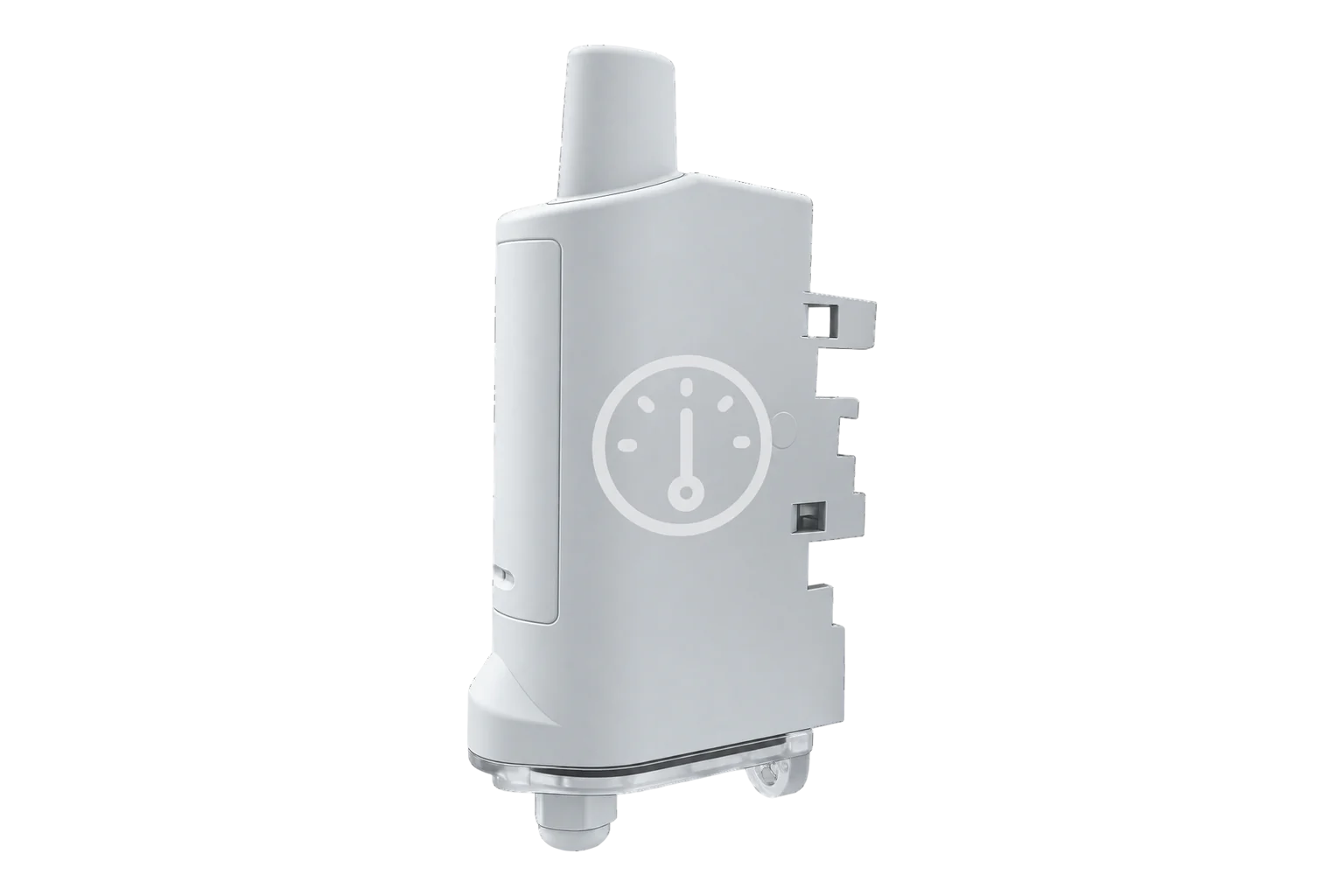
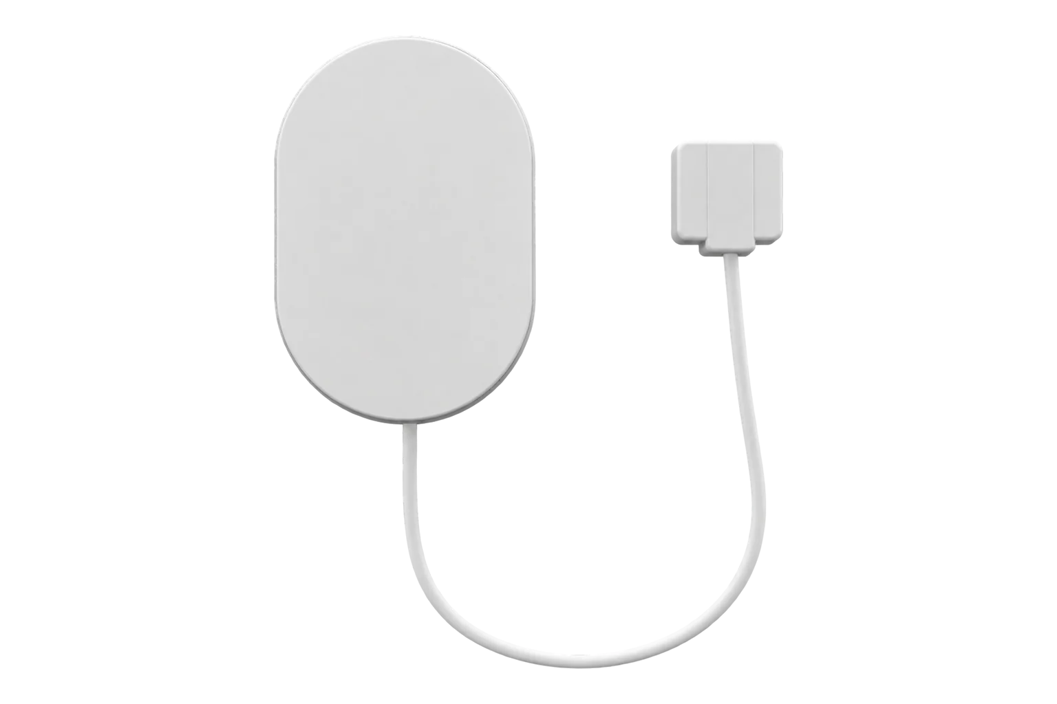
- ZMB-31, Modbus RTU over RS-485, up to 30 registers, cable runs to 1,000 m Modbus Interface datasheet
- On site
- ZGW-20 Gateway, a BACnet/IP and Modbus client, and a Modbus TCP and MQTT source for meter data acquisition Edge
Modbus to BACnet, and which direction the Gateway can run it
Edge is a BACnet/IP client and a Modbus client, so it reads BACnet and Modbus devices. It is also a Modbus server, so another system can read what it has collected. It does not serve BACnet. Decide which way the data has to travel before choosing anything, because that decides whether Edge or the BMS is the client.
| Edge reads the device | The BMS reads Edge | |
|---|---|---|
| Protocols | Modbus RTU and TCP, BACnet/IP, OPC UA, M-Bus, pulse, 4-20 mA | Modbus TCP, MQTT, HTTP |
| Who is the client | Edge | The BMS or SCADA system |
| Watch for | A bus that already has a master | A point list the BMS has to be told about |
Hardware for meter data acquisition
One interface per physical layer. The Gateway is what makes them one point list.
An RS-485 Modbus RTU bus of meters or equipment, read wirelessly
1 per bus up to 30 registers
Modbus RTU, function codes 1 to 6, 15 and 16, coil, discrete, input and holding registers, 300 to 115,200 baud
Runs Edge: reads every interface, holds one point list, and serves it onward
1 per site up to 250 wireless devices
Zigbee, Ethernet, cellular, RS-485, with Modbus, BACnet and MQTT
If the site has M-Bus meters
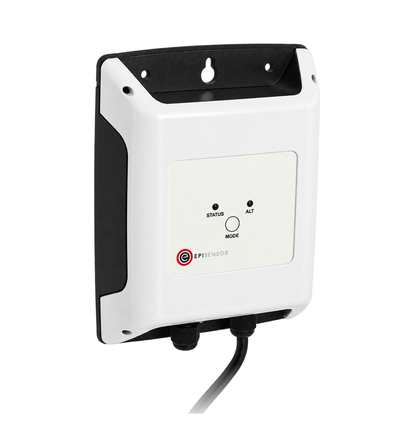
A wired M-Bus heat or utility meter
1 per meter one connected meter each
If the site has pulse-output meters
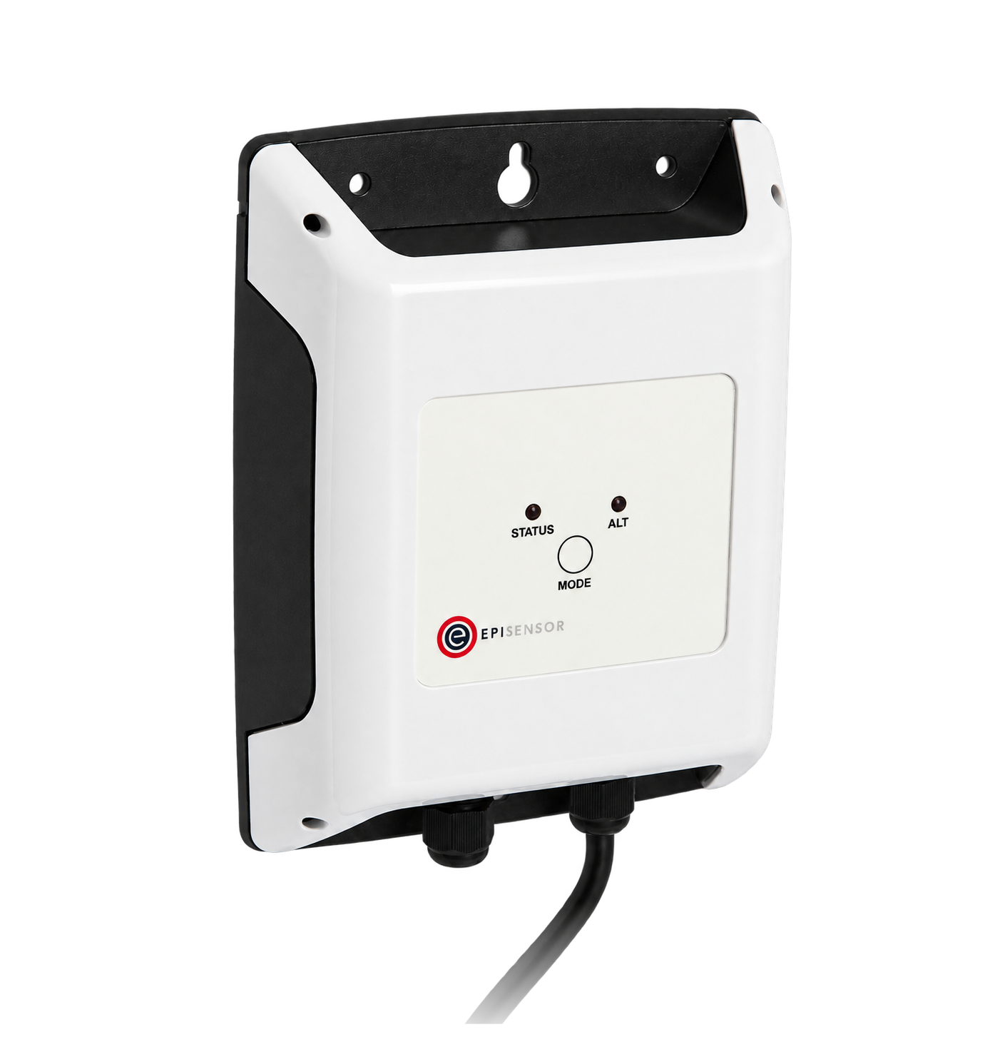
A meter whose only output is a pulse
1 per meter two channels on the ZPC-22
If the site has analogue instruments
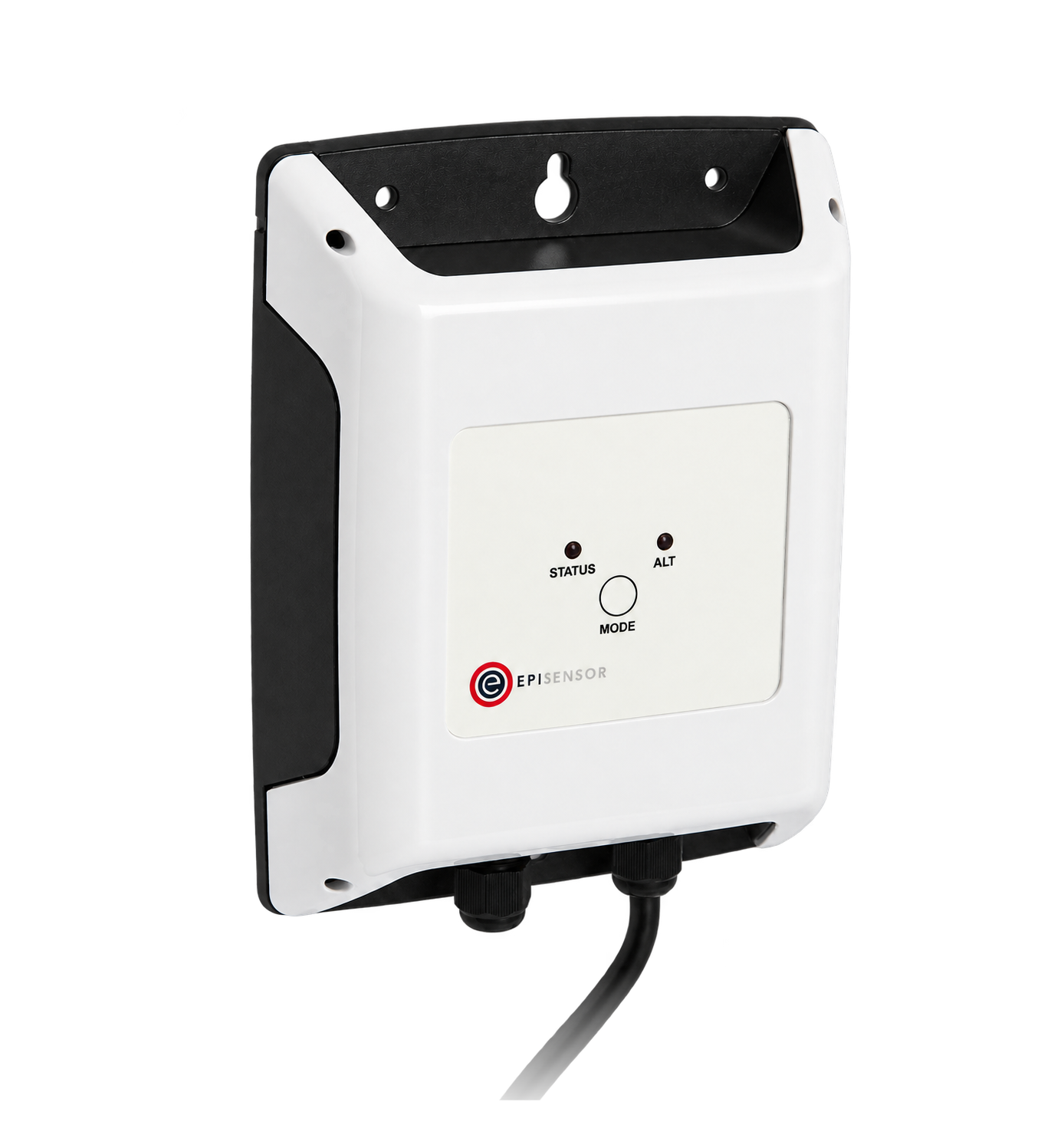
An instrument with a 4-20 mA output and no digital interface
1 per loop externally powered loop
What each interface is responsible for
Each physical layer has its own interface, and the Gateway turns all of them into one list of points with units.
From field measurement to Edge
Each field signal reaches its named EpiSensor interface, reports through the site Gateway and is handled locally in Edge.
- Modbus
- Zigbee
- Edge
- Platforms
| Position | What it tells you | Reference | Sensor |
|---|---|---|---|
| Modbus RTU equipment | Meters, drives and controllers that already have registers | One master per bus: check nothing else is already polling it Modbus | ZMB-31 (on this page) |
| M-Bus meters | Heat and utility meters with their own calculated records | One meter per interface M-Bus Interface datasheet | ZHM-21 (on this page) |
| Pulse outputs | Meters with no digital interface at all | Pulse weight, width and voltage from the meter's manual Pulse Counter datasheet | ZPC-20 (on this page) |
| Analogue instruments | Transmitters whose only output is a current loop | Range, scaling and loop power recorded per instrument Analogue Signal Sensor datasheet | ZIO-20 (on this page) |
| The onward interface | What the BMS or SCADA system reads, and how | Modbus server, MQTT or HTTP from the Gateway Edge | ZGW-20 (on this page) |
Give each RS-485 bus one master. If a BMS is already polling the RS-485 bus, adding a second master breaks both. Either read from the BMS instead, or give the meters their own bus.
Serve BACnet points onward over Modbus TCP, MQTT or HTTP. Edge reads BACnet/IP as a client and does not act as a BACnet server, so a BMS that reads from Edge uses one of those interfaces.
The settings both ends have to agree on
Every one of these exists in two places. Where they disagree, the symptom is usually silence or a plausible wrong number.
| Setting | Typical value | Where to check |
|---|---|---|
| Unit or slave address | 1 to 247 | The device's own configuration. Two devices with the same address on one bus produce intermittent nonsense. |
| Baud rate, parity and stop bits | 9,600 or 19,200, 8N1 | The device's manual, then the same settings on the interface. |
| Register base | Zero-based offsets | The vendor's map: a register numbered 40001 is usually holding-register offset 0. |
| Function code | 3 for holding, 4 for input | The map. Reading the right number with the wrong function code returns an exception, or someone else's value. |
| Data type and word order | 32-bit float, high word first | The map, then a value you can predict. A wrong word order gives a number that looks like data. |
| Scale and unit | The device's own multiplier | The map, and a comparison with the device's display. |
| Poll interval | 15 to 60 seconds per device | The bus load: more devices and more registers need a longer cycle. |
| Onward interface | Modbus TCP, MQTT or HTTP | What the BMS or SCADA system can read, agreed with whoever maintains it. |
Commissioning checks
These checks catch the failures that look like success.
-
One raw exchange is understood
Capture one request and its response, and reconcile it by hand against the vendor's register map.
Pass when every byte of the response is accounted for, including the scaling.
-
Values are checked independently
Compare each point with the device's own display or with a separate instrument.
Pass when the values match, in the same units, at two different operating points.
-
The bus holds up at the polling rate
Run the intended poll cycle for a day and count errors and timeouts.
Pass when the error rate is stable and low, and no device drops out.
-
A broken link is visible everywhere
Disconnect one device and watch both Edge and the consuming system.
Pass when both show the point as stale or missing rather than holding the last value.
-
Writes are proven and bounded
For any write, test permission, range limits, acknowledgement, timeout, local override and the behaviour on failure.
Pass when every one of those is demonstrated, and what happens on failure is written down.
Limits of this measurement
A protocol carries values. It does not agree what they mean.
- Modbus does not define a universal register map or engineering unit for any device.
- RS-485 is a physical and electrical layer. Modbus is an application protocol, and it also runs over other transports.
- Protocol translation does not make a Modbus register, a BACnet object and an MQTT topic mean the same thing.
- Edge is a BACnet/IP client, not a BACnet server, and it does not do BACnet MS/TP.
Sources
- Modbus specifications and implementation guides (opens in a new tab) (opens in a new tab) Modbus Organization
- An introduction to Modbus (opens in a new tab) (opens in a new tab) Modbus Organization
- Modbus Interface datasheet (opens in a new tab) EpiSensor. Specifications, ranges and ordering codes.
Related
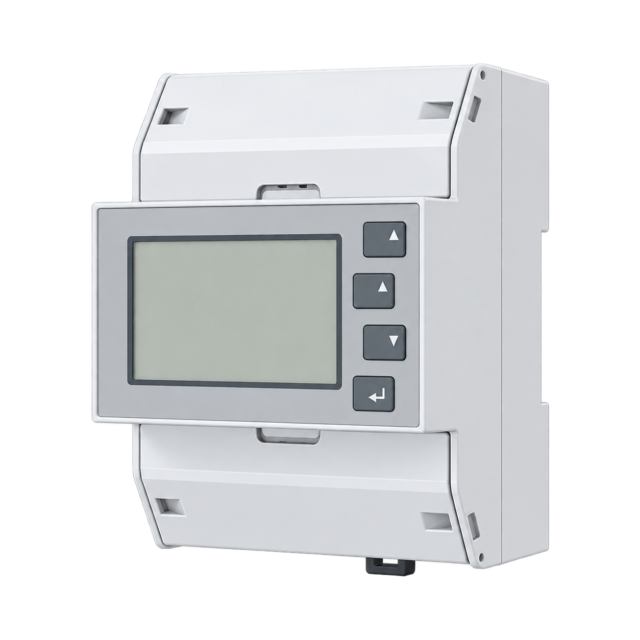
Decide which direction your integration should run
An engineer can say which devices can be read as they are, and which direction the integration should run.