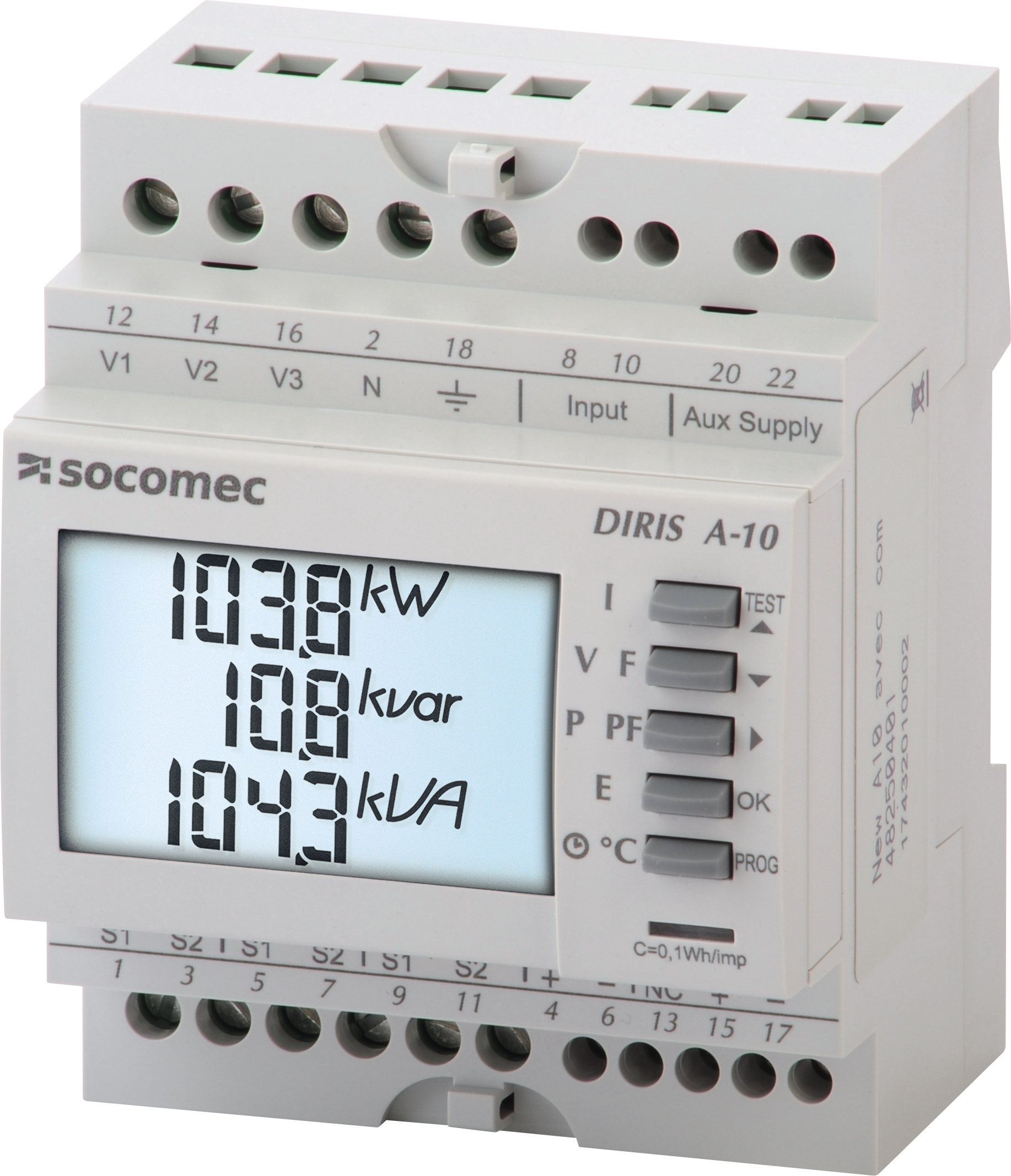
Socomec DIRIS A-10
Power and energy meter
The DIRIS A-10 is a four-module DIN-rail power monitoring device that measures low-voltage networks through 5 A current transformers. Reference 48250401 has an RS-485 port speaking Modbus RTU on terminals 15 and 17; reference 48250400 has no communication port. Socomec's communication table V202.81 lists decimal addresses with 32-bit values for voltage, current, power and energy, and 16-bit values for frequency, power factor and THD.
Compatibility
Compatible with EpiSensor Edge over Modbus RTU
Socomec documents RS-485 Modbus RTU for reference 48250401 and publishes a register table with decimal and hexadecimal addresses, register counts, units and data types. This is documented compatibility, without a physical Edge test.
DIRIS A-10 with RS485 Modbus, reference 48250401, using communication table V202.81 (February 2025) as a best-effort starting map. The A-10 table names its blocks READ but prints no function code or word order, so the first read is a single-register frequency point compared with the display. Reference 48250400 has no communication port. Read-only monitoring.
Connect it with
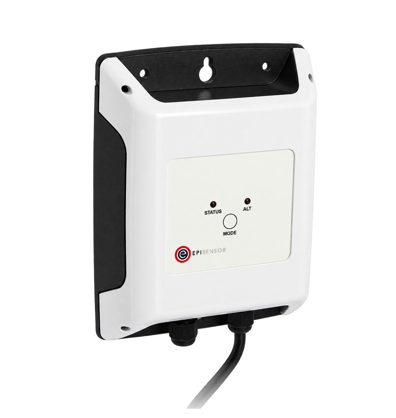
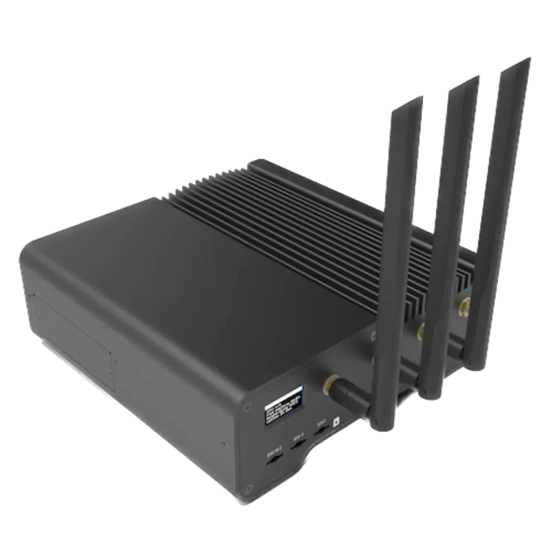
For reference 48250401, the DIRIS A-10 with the RS-485 communication port
- Modbus
- Edge
- Platforms
Models
| Models | Interface | Route into Edge |
|---|---|---|
| DIRIS A-10 with RS485 Modbus (48250401) | Three voltage inputs and three 5 A CT inputs; RS-485 Modbus RTU on terminals 15 (+) and 17 (-); one pulse output on 4 and 6; one tariff input on 8 and 10 | Read the communication table V202.81 registers on the serial path. |
| DIRIS A-10 (48250400) | Same measurement and display, without the RS-485 port | No Modbus path; the register table in this guide cannot be read from this reference. |
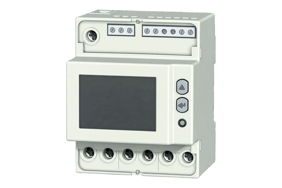
| DIRIS A-20, A-30, A-40 and A-41 | Larger DIRIS A meters with their own communication modules and tables | Not covered by this map. The A40 and A41 have their own device page. |
Specifications
Choose the A-10 for a single low-voltage feeder or board measured through CTs where a modular meter with a display and RS-485 is enough. Order 48250401 for communication; 48250400 is the display-only reference. Both carry the same IEC 61557-12 measurement, a two-tariff input and a pulse output.23
- Exact references
- DIRIS A-10 with RS485 Modbus: 4825 0401. DIRIS A-10 without communication: 4825 0400.23
- Networks
- Three-phase three or four wire, two-phase and single-phase, set as 1BL, 2BL, 3BL, 3NBL, 4BL or 4NBL in the programming menu. Balanced networks can use one CT; unbalanced three-wire networks can use two.123
- Current inputs
- Through CTs with a 5 A secondary and a primary from 5 to 9999 A. Minimum measuring current 5 mA; permanent overload 6 A; input consumption below 0.6 VA.23
- Voltage inputs
- Direct connection, 50 to 520 V AC phase to phase and 50 to 300 V AC phase to neutral; 45 to 65 Hz. Fuse each voltage input with 0.5 A gG.23
- Accuracy
- Active energy class 0.5S to IEC 62053-22; reactive energy class 2 to IEC 62053-23. PMD to IEC 61557-12. Measurements update every second.23
- Auxiliary supply
- Separate supply on terminals 20 and 22: 110 to 277 V AC, 50/60 Hz in both documents; the catalogue also lists 120 to 300 V DC. Check the rating label on the installed meter.23
- RS-485
- Reference 48250401 only. Modbus RTU (JBUS) over two-wire half-duplex RS-485 on terminals 15 (+) and 17 (-). Address 1 to 255 in the menu; 2400 to 38400 bit/s; odd, even or no parity; one or two stop bits.23
- Other interfaces
- Pulse output on 4 (+) and 6 (-) to IEC 62053-31 class A and B, up to 30 V DC and 27 mA. Tariff input on 8 and 10: 0 V AC selects tariff 1 and an AC voltage selects tariff 2. Internal temperature sensor.23
Interface
Documented measurements and integration boundaries for DIRIS A-10.
- Addresses in the table are decimal PDU addresses with the hexadecimal beside them: 50520 is 0xC558 and goes on the wire as C5 58. Read every point with FC03 and do not mix blocks in one request.
- Frequency at 51287 (0xC857): one register, U16, hundredths of a hertz. The safest first read, because it needs no word order.
- Phase-to-phase voltage U12, U23, U31 at 50514, 50516 and 50518, and phase-to-neutral voltage V1, V2, V3 at 50520, 50522 and 50524: two registers each, U32, hundredths of a volt.
- Frequency as a 32-bit value at 50526: two registers, U32, hundredths of a hertz.
- Current I1, I2, I3 and neutral In at 50528, 50530, 50532 and 50534: two registers each, U32, milliamps, in the block Socomec marks as affected by the current transformers.
- Total active power at 50536 (S32, units of 10 W, signed for import and export), total reactive power at 50538 (S32, units of 10 var), total apparent power at 50540 (U32, units of 10 VA) and total power factor at 50542 (S32, divide by 1000; negative is leading, positive lagging).
- Active power per phase at 50544, 50546 and 50548: S32, units of 10 W. Reactive power per phase follows at 50550 to 50554 and apparent power at 50556 to 50560.
- Energy at 50780 positive active (Ea+), 50786 negative active (Ea-), 50782 positive reactive and 50788 negative reactive: two registers each, U32, kWh or kvarh in whole units. Socomec labels these counters partial.
- Tariff energy: current tariff number at 50849, then active energy for tariff 1 and tariff 2 at 50850 and 50852 (U32, kWh).
- Total harmonic distortion at 51536 to 51544 (U12 to U31, V1 to V3, I1 to I3): one register each, U16, tenths of a percent.
- Identity: 50000 holds "SOCO" in four registers, 50006 the table version, 50007 the software version and 50050 the product name in eight registers.
- Leave the setup table at 36352, the reset command at 1024 and the action register at 57856 out of the polling configuration. They accept writes with lock level NONE and change the CT ratio, zero counters or restore factory settings.
Assessment
DIRIS A-10 with RS485 Modbus, reference 48250401, using communication table V202.81 (February 2025) as a best-effort starting map. The A-10 table names its blocks READ but prints no function code or word order, so the first read is a single-register frequency point compared with the display. Reference 48250400 has no communication port. Read-only monitoring.
- InteroperabilitySupported with conditions
- Modbus RTU on RS-485 is documented and the table gives decimal and hexadecimal addresses, register counts, units and data types. The A-10 table itself omits the function code and word order, which come from Socomec's conventions in its other tables and need a display check.124
- AccuracySupported with conditions
- Class 0.5S active energy through 5 A CTs, per-phase voltage, current and power, signed power, import and export energy, two tariffs and THD. Accuracy depends on the CTs and correct wiring, and the energy counters are resettable with 1 kWh resolution over Modbus.123
- SecurityLimited
- The front panel has a programming code, but the communication table marks the setup, reset and action tables writable with lock level NONE. Plain Modbus RTU has no authentication or encryption, so the bus needs physical protection and a read-only client.12
- ReliabilitySupported with conditions
- One-second updates, a wiring test that reports CT and voltage errors, immunity to IEC 61326-1 and a published supply tolerance. Treat failed reads as missing data.23
- RuggednessSupported with conditions
- Indoor DIN-rail meter for -10 to +55 °C, up to 2000 m, IP52 front, 2 g vibration from 10 to 100 Hz and installation category III; it belongs in an enclosure.23
- ScalabilitySupported with conditions
- Addresses 1 to 255, speeds to 38400 bit/s and a multidrop RS-485 diagram are documented. Socomec's retained documents give no device count or cable length, so bus loading and polling rate depend on the installation.23
- LifecycleNot yet assessed
- The 2026 catalogue lists both references and a 30-year calibration guarantee, but nothing about firmware support or end of sale.3
Setup
Read frequency from decimal address 51287
DIRIS A-10 communication table V202.81 lists frequency F at decimal 51287 (0xC857) in the block not affected by current and voltage transformers: one register, U16, unit Hz 10^-2. Use that map as the starting point and compare the result with the display.
- Request
- 01 03 C8 57 00 01 0B BA: Modbus address 1, FC03, start 0xC857, one register, RTU CRC. Change the first byte to the meter's Adr setting and recalculate the CRC.
- Address convention
- The table address is the zero-based PDU address: decimal 51287 goes on the wire as C8 57. A client that numbers registers from one shows it as 51288, and a 4xxxx-style client may need 451288. Do not subtract one from the table value.
- Length and type
- One register, U16. A single register has no word order to get wrong, which is why this is the first read.
- Synthetic response
- 01 03 02 13 88 B5 12: two data bytes, 13 88.
- Decode
- 0x1388 is 5000; the unit is hundredths of a hertz, so 5000 / 100 = 50.00 Hz.
- Acceptance
- Keep the point when it agrees with frequency on the display at the same time. If the meter returns exception 01 (illegal function), the function code assumption is wrong; if it returns 02, check the address convention and installed reference before trying other points.
Acceptance: The response bytes are a synthetic decoder check, not a captured meter reply. The A-10 table prints no function-code number; FC03 is how Socomec defines the READ label in its current tables. A real reply must agree with the display before 32-bit voltage, current, power and energy points are enabled.
-
Identify the meter
Read the reference on the side label. 48250401 has the RS-485 port and a communication activity indicator on the display; 48250400 has no port. Record the software version shown at the end of the programming menu.
-
Run the connection test first
The TEST function reports Err 0 when the wiring is correct, Err 1 to Err 3 for a reversed CT and Err 4 to Err 6 for swapped voltages. It needs current and voltage on every phase and a power factor between 0.6 and 1. Clear any error before you collect power or energy.
-
Read the serial settings from the programming menu
Enter the programming menu with the access code (100 in the instructions unless it has been changed) and note Adr, bdS, PAr and StOP. Enter the same address, speed, parity and stop bits in the Edge serial client, then leave the menu without changing anything else.
-
Wire the RS-485 pair
Connect + to terminal 15 and - to terminal 17 with shielded twisted pair, as in Socomec's LIYCY-CY drawing. Fit a 120 ohm resistor between + and - at the ends of the line where needed. Terminal 13 is marked NC on the meter and in the instructions but 0 V in the catalogue drawing, so follow the label on the installed unit for the shield.
-
Make one frequency read
Send FC03 to address 51287 for one register and divide the result by 100, as in the worked read below. Compare it with frequency on the display under the V F key.
-
Confirm the word order, then add points
Read V1 at 50520 as two registers, high word first, and compare it with the display before enabling other 32-bit points. Then add current, power and energy from the same block, log Ea+ and Ea- separately where export is possible, and keep FC06 and FC16 out of the configuration.
Common questions
- Which register block should I use for current and power?
- Use the 32-bit block from 50512, which Socomec marks as affected by the current and voltage transformers, so currents, powers and energy are on the primary side. The table also has a 16-bit block from 51280 marked not affected by the transformers, with currents in mA in one register; it does not explain that block further, so use it for frequency and power factor, where the CT ratio makes no difference.1
- What function code and word order does the A-10 use?
- The A-10 table marks its measurement blocks READ and its setup blocks READ, WRITE and WRITE_MANY without printing function-code numbers or a word order. Socomec's current tables define those labels as functions 3, 6 and 16 and decode U32 and S32 values high word first. Start with the one-register frequency read, then confirm the word order on a 32-bit voltage before adding more points.14
- Can the energy counters be reset?
- Yes. The table labels the energy at 50780 to 50788 partial, the display's rSET item zeroes counters, and the reset command at 1024 can clear kWh+, kWh-, kvarh and the hour meter over Modbus. Store each reading with its timestamp and treat a drop as a reset, not negative consumption. The counters move in whole kWh, which is coarse for short intervals on small loads.12
- Should I use the non-resettable energy rows at 51311 to 51314?
- Not without Socomec's confirmation. The table lists total positive and negative active and reactive energy there as single U16 registers with the unit written as Wh / 1E-06, which cannot hold a meter-sized total as printed. Use the 32-bit counters and compare them with the display.1
- Is the tariff input a dry contact?
- No. With no voltage on terminals 8 and 10 the meter uses tariff 1, and an AC voltage selects tariff 2. The instructions give 110 to 277 V AC and the catalogue 200 to 277 V AC, so have the installer check the circuit against the installed meter. The current tariff is readable at 50849.123
Related devices

Sources
- DIRIS A-10 multifunction meter Modbus communication table V202.81 (February 2025 issue) (opens in a new tab)
- DIRIS A-10 operating instructions 538847 E (multilingual, with programming menu and technical characteristics) (opens in a new tab) (PDF)
- DIRIS A-10 Power Monitoring Device catalogue pages PCG051 EN V01 (January 2026) (opens in a new tab) (PDF)
- DIRIS Digiware I-35 communication table CMT 1.14.1, Documentation tab: Socomec's definitions of the READ, WRITE and WRITE_MANY functions and of the U32, S32 and string types (opens in a new tab)
Further reading
- ToolModbus register address translator
- ToolModbus data decoder
- GuideSocomec DIRIS A40 and A41: the larger panel meters
- GuideSocomec COUNTIS E53: CT-connected energy meter
- GuideSocomec COUNTIS E23 and E24: direct 80 A meters
- ToolRS-485 termination and bias
- ManufacturerSocomec devices
- ProtocolModbus devices and register maps
- CategoryEnergy meters
Product names and trademarks belong to their owners. Publication does not imply endorsement or a commercial relationship.