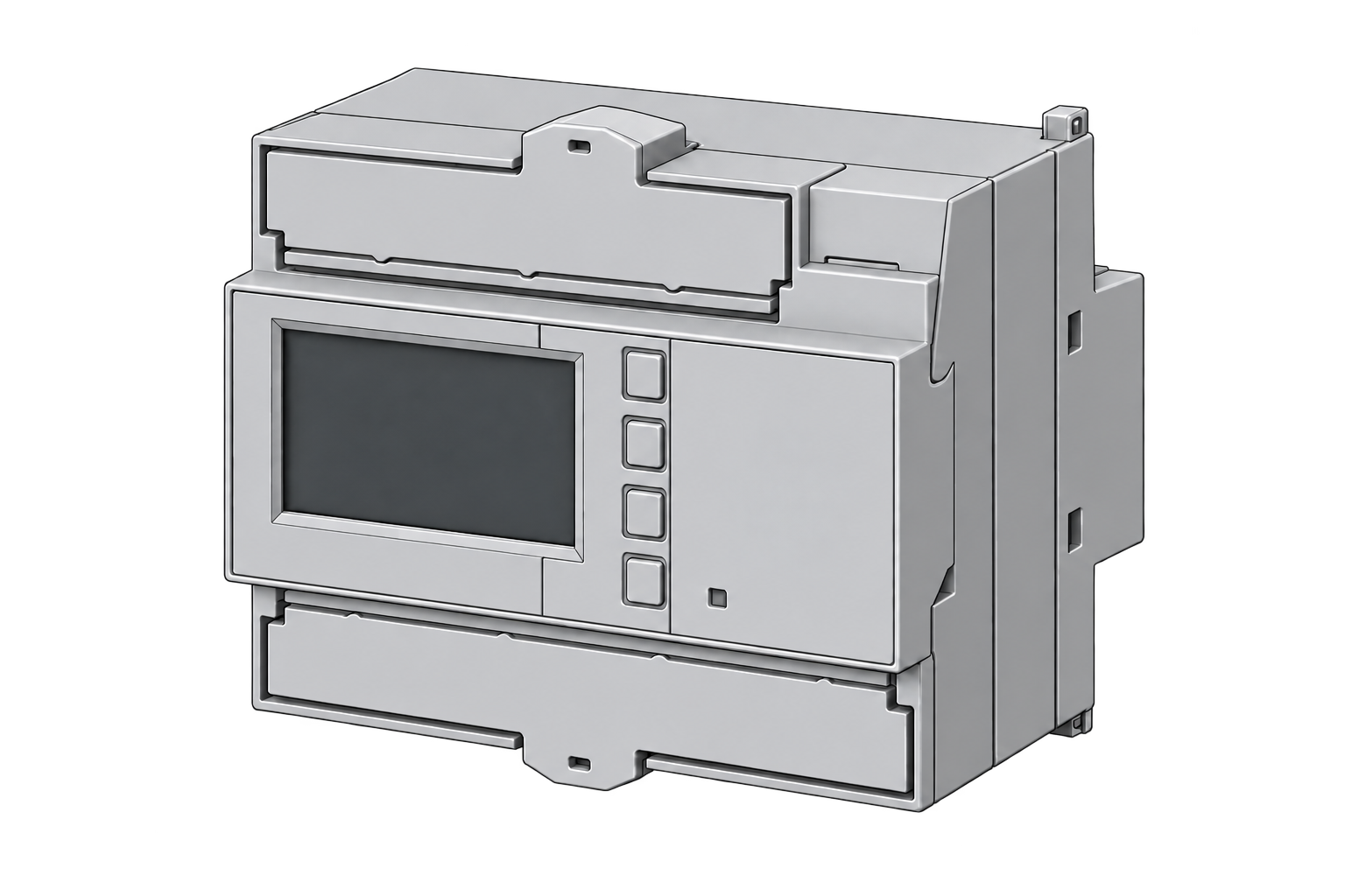
Siemens SENTRON PAC2200
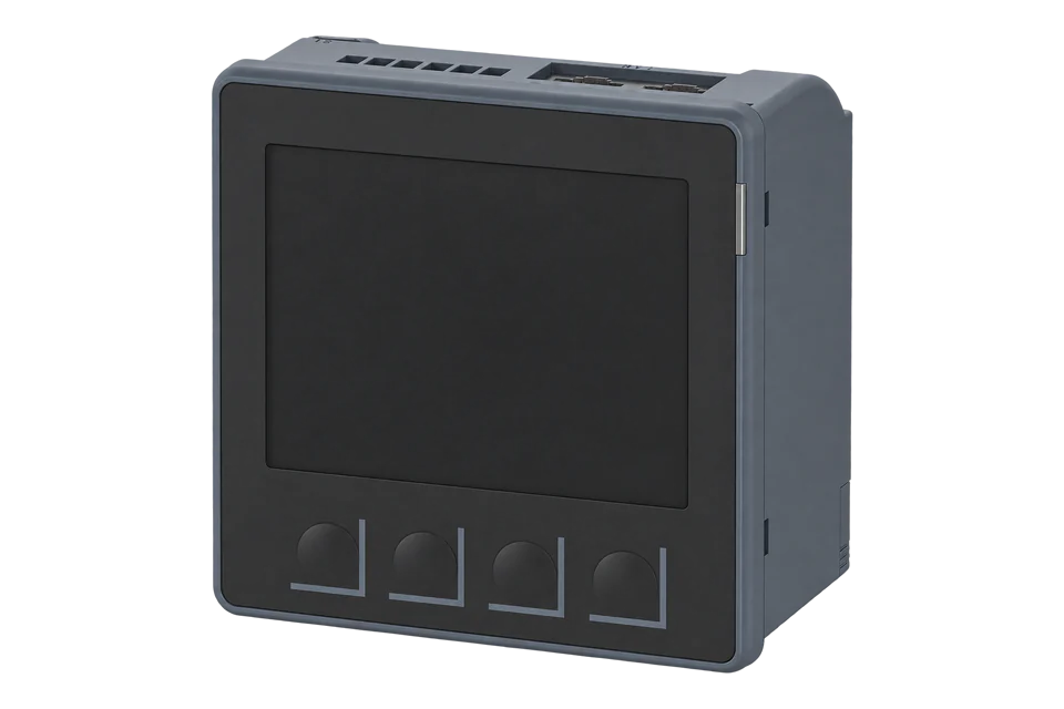
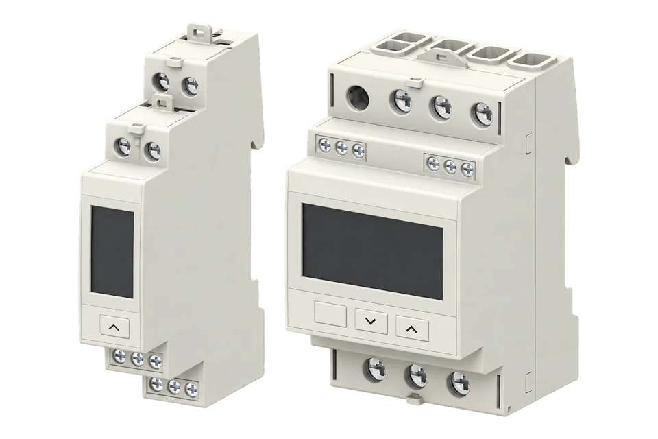
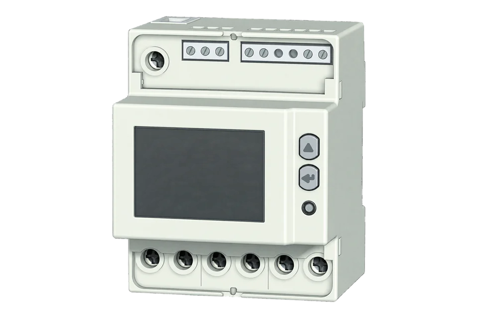
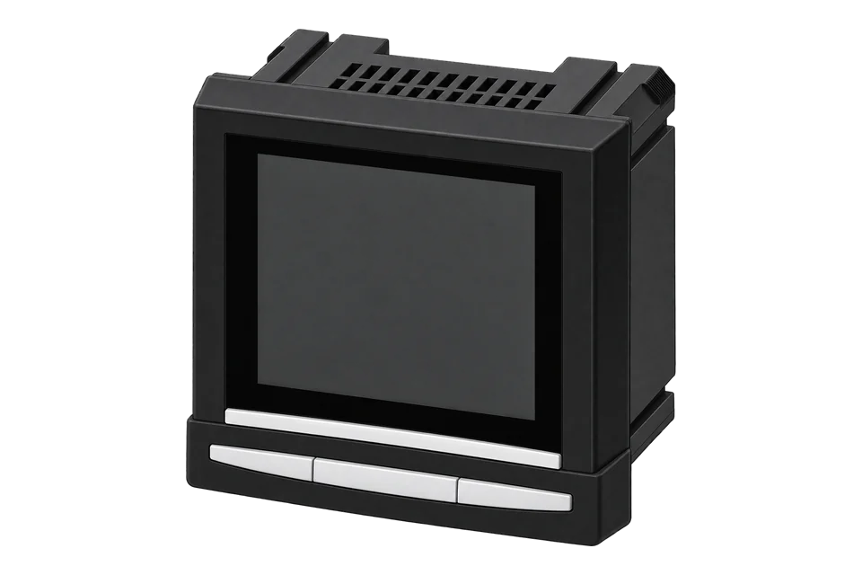
Three-phase power meter
A DIN-rail three-phase meter. Edge reads voltage, current and power over Modbus. Match the installed ordering code in the model table.
Compatibility
Compatible
Siemens publishes the PAC2200 interface and register table. Edge polls the documented measurements as a Modbus client.
The PAC2200 family is compatible over Modbus. This guide commissions the Ethernet model 7KM2200-2EA30-1EA1. RS-485, 65 A, CLP and MID variants are in the table, and they do not share this interface.
Connect it with
-
Gateway ZGW-20From €899 ex VAT Configure Gateway

Ethernet PAC2200 on a protected site LAN
- Modbus
- Edge
- Platforms
Specifications
A three-phase DIN-rail power meter for 5 A current transformers, ordered with either an Ethernet port for Modbus TCP or an RS-485 port for Modbus RTU. It is powered from the measuring voltage and keeps its energy counters through a power cut.12
Interface
This register map is for the 7KM2200-2EA30-1EA1. 7KM2200-2EA30-1DA1 and other variants have their own interfaces and are not covered here.
Communication settings
- Interface
- Ethernet, Modbus TCP, 5 A transformer inputs, 400 V L-L / 230 V L-N
- Read with
- FC04 (input registers)
- Word order
- High word first on every value
- Addresses
- Zero-based PDU addresses, as sent on the bus
- Route into Edge
- Edge Modbus client over a protected Ethernet network
From PAC2200 Equipment Manual, 12/2022, L1V30415167B-062.
Register map
| Point | Address | Hex | Format | Scale | Unit |
|---|---|---|---|---|---|
| Voltage L1-N | 1 | 0x0001 |
FLOAT32 | ×1 | V |
| Voltage L2-N | 3 | 0x0003 |
FLOAT32 | ×1 | V |
| Voltage L3-N | 5 | 0x0005 |
FLOAT32 | ×1 | V |
| Voltage L1-L2 | 7 | 0x0007 |
FLOAT32 | ×1 | V |
| Voltage L2-L3 | 9 | 0x0009 |
FLOAT32 | ×1 | V |
| Voltage L3-L1 | 11 | 0x000B |
FLOAT32 | ×1 | V |
| Current L1 | 13 | 0x000D |
FLOAT32 | ×1 | A |
| Current L2 | 15 | 0x000F |
FLOAT32 | ×1 | A |
| Current L3 | 17 | 0x0011 |
FLOAT32 | ×1 | A |
| Active Power L1 | 25 | 0x0019 |
FLOAT32 | ×1 | W |
| Active Power L2 | 27 | 0x001B |
FLOAT32 | ×1 | W |
| Active Power L3 | 29 | 0x001D |
FLOAT32 | ×1 | W |
| Reactive Power L1 | 31 | 0x001F |
FLOAT32 | ×1 | VAr |
| Reactive Power L2 | 33 | 0x0021 |
FLOAT32 | ×1 | VAr |
| Reactive Power L3 | 35 | 0x0023 |
FLOAT32 | ×1 | VAr |
| Power Factor L1 | 37 | 0x0025 |
FLOAT32 | ×1 | - |
| Power Factor L2 | 39 | 0x0027 |
FLOAT32 | ×1 | - |
| Power Factor L3 | 41 | 0x0029 |
FLOAT32 | ×1 | - |
| Frequency | 55 | 0x0037 |
FLOAT32 | ×1 | Hz |
| Total Apparent Power | 63 | 0x003F |
FLOAT32 | ×1 | VA |
| Total Active Power | 65 | 0x0041 |
FLOAT32 | ×1 | W |
| Total Reactive Power | 67 | 0x0043 |
FLOAT32 | ×1 | VAr |
| Total Power Factor | 69 | 0x0045 |
FLOAT32 | ×1 | - |
| Neutral Current | 71 | 0x0047 |
FLOAT32 | ×1 | A |
Assessment
The assessment is for the Ethernet 5 A model read over Modbus TCP. Other PAC2200 versions on this page may differ.
- InteroperabilityWell supported
- Siemens publishes the Modbus TCP register offsets, data types and units.124
- AccuracySupported with conditions
- The main three-phase values. Input type, accuracy, wiring mode and counter format depend on the ordering code, so match it to the model table.12
- SecuritySupported with conditions
- A password, a hardware write lock, an IP filter and a configurable TCP port. Modbus TCP itself has no encryption or authentication, so keep the meter on a separate network segment.24
- ReliabilityWell supported
- Powered from the measuring voltage (100-230 V AC ±20 %), and the counters survive a power cut. 6.5 kV impulse withstand, CAT III and EN 61326-1 immunity, with the bus cable grounded.12
- RuggednessSupported with conditions
- A DIN-rail meter for an indoor panel. The panel, enclosure and temperature decide where it can go.12
Edge template
This JSON file supplies the register map. Applying it to an existing meter replaces its sensor list while retaining the site connection, unit ID and enable state.
| Model | Connection | Points | Version | Updated | Download |
|---|---|---|---|---|---|
| 7KM2200-2EA30-1EA1 | Ethernet, Modbus TCP, 5 A transformer inputs, 400 V L-L / 230 V L-N | 24 | 1.0.0 | Download |
Downloads need a signed-in account with Edge download access.
Use the template in Edge
- Import the JSON file
In Edge, open Settings, then Devices and Templates. Choose Import JSON and select the downloaded file. Confirm that the model and template name match your device.
- Load the map for your meter
For a new Modbus device, use Load Template before entering the manufacturer or model; it fills those fields and the register list. Set the name, site connection and unit ID, check the polling enable state, then test before saving. For an existing device, apply only to the matching model; this replaces its sensor list but retains its connection, unit ID and enable state.
- Test a reading
Use Test in the wizard and compare a known reading with the meter display. Check its unit, sign and scale, then confirm that timestamps keep advancing. These starter maps are read-only and leave exports off until you configure them.
Setup
Read L1-to-neutral voltage
Use this bounded check only on an already commissioned meter. It verifies one live measurement without writing a register or changing the PAC2200 configuration.
- Function
- FC03 or FC04 read
- Siemens offset
- 1
- PDU start
- 1 / 0x0001
- 4xxxx display
- 40002 when the client uses 40001-based notation
- Length
- 2 registers
- Decode
- IEEE-754 float32
- Engineering unit
- V
- Scale
- multiplier 1 · offset 0
Acceptance: Compare the decoded value with the simultaneous L1-N reading on the meter display. Retain the raw response, configured byte and word order, timestamp and observed difference before mapping further points.
-
Identify the model
Read the full ordering code and firmware before choosing a map: the PAC2200 comes in several interface versions, and they are not interchangeable.
-
Set the address and network settings
Confirm the IP address, Modbus TCP port and unit ID. Port 502 is the default, not a value to assume on an existing site. Allow traffic from Edge to the meter only.
-
Connect the meter
Connect the Ethernet version to the site network, or wire and terminate the RS-485 version’s bus. Leave the hardware write protection on.
-
Check one value
Read the voltage from the check above with Siemens’ protocol offset 1 (display reference 40002). Compare units and signed power with the front panel, and watch fresh timestamps over several polls.
-
Add current, power and energy
Add L1 current at offset 13 and total active power at 65: FC03 or FC04, two registers, float32 in A and W, multiplier 1. For an energy display, read import tariff 1 at 2801 and tariff 2 at 2803, two-register float32 in Wh; divide by 1000 for kWh. For calculations, use the higher-resolution four-register Double counters at 801/805 (import T1/T2) and 809/813 (export T1/T2), in Wh. Use a 64-bit decoder for those counters; they are separate from a native 32-bit Edge map. Compare interval changes with the display and keep write protection enabled.
Related devices

Sources
- SENTRON PAC2200 7KM2200-2EA30-1EA1 product details (opens in a new tab)
- PAC2200 Equipment Manual, 12/2022, L1V30415167B-06 (opens in a new tab) (PDF)
- SENTRON PAC2200 7KM2200-2EA30-1DA1 product details (opens in a new tab)
- Modbus specifications and implementation guides (opens in a new tab)
Further reading
- ApplicationTransformer and distribution-board monitoring
- ApplicationMulti-site energy monitoring
- ApplicationHVAC energy monitoring
- ApplicationBMS and SCADA meter integration
- ToolModbus register address translator
- ToolModbus data decoder
- ToolModbus function and exception reference
- GuideModbus commissioning over RS-485
- GuideIoT interoperability in multi-vendor systems
- ToolRS-485 termination and bias
- ManufacturerSiemens devices
- ProtocolModbus devices and register maps
- CategoryEnergy meters
Product names and trademarks belong to their owners. Publication does not imply endorsement or a commercial relationship.