Siemens SENTRON PAC3220
Power and energy meter
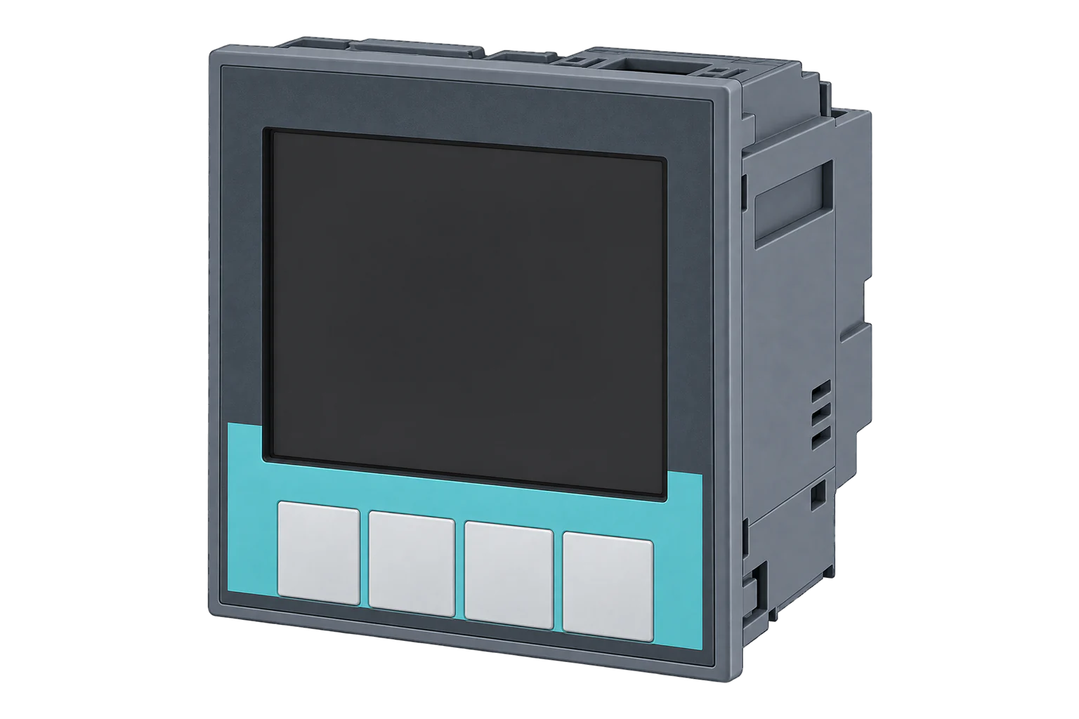
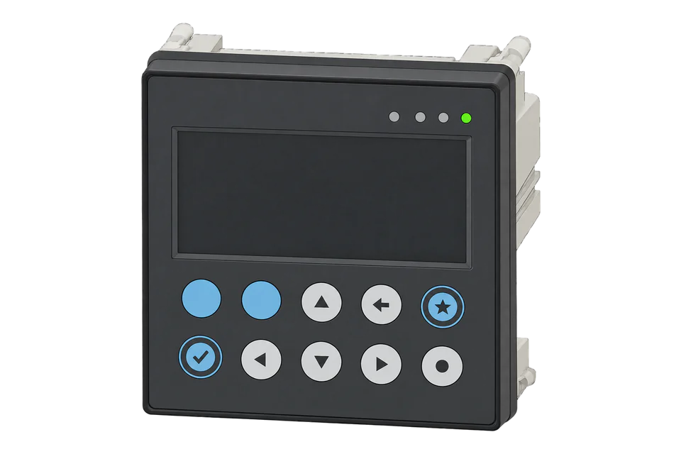
The PAC3220 is a CT-connected panel meter with two switched Ethernet ports and local Modbus TCP. Its hardware write-protection switch can preserve a monitoring-only configuration while Edge reads power, demand and energy.
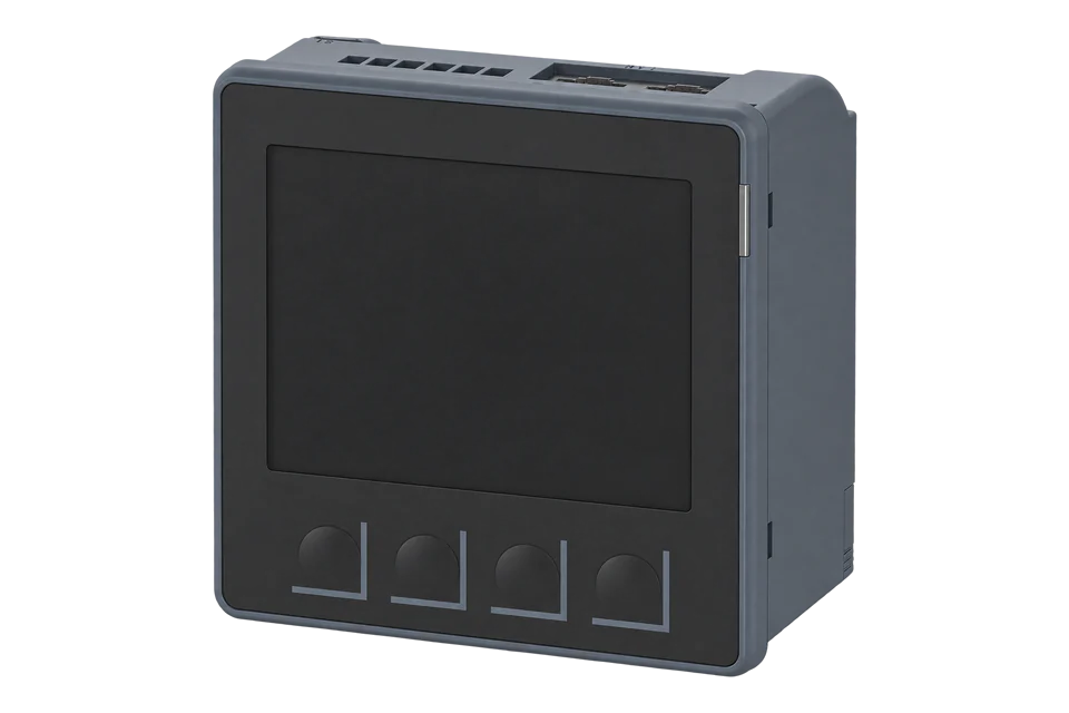
- Modbus TCP
Power and energy meter
Compatibility
Compatible through Modbus TCP
Siemens documents Modbus TCP measurement reads with literal offsets and floating-point types. Edge uses the Ethernet connection path below.
PAC3220 non-MID family covered by the July 2024 PAC3120/PAC3220 manual. Check the full 7KM3220 order number and supply variant. PAC3120, PAC3220 MID and optional expansion modules have separate interface or certification scope.
Connect it with
-
Gateway ZGW-20From €899 ex VAT Configure Gateway
-
Evaluation Gateway on a Raspberry Pi Edge with one device licensedFree Set up Evaluation Gateway on a Raspberry Pi

For the standard PAC3220 Ethernet interface
- Modbus
- Edge
- Platforms
Models
| Models | Interface | Route into Edge |
|---|---|---|
| PAC3220 | Built-in Ethernet with two switched ports and Modbus TCP | Use this guide for the non-MID meter and its matching manual. |
| PAC3220 with RS-485 expansion | Optional module adds a serial path | Use the expansion module manual and its actual settings; PAC3120 serial defaults are not evidence for this module. |
| PAC3120 / PAC3220 MID | Different native interface or metrological certification scope | Use the exact model manual and approval requirements rather than inferring them from PAC3220. |
Specifications
The PAC3220 separates commissioning access from routine collection with a physical write-protection switch. Once ratios and network settings are correct, read-only monitoring can continue with changes blocked. Its Modbus tables use offsets, and the device checks complete multi-register access: a request beginning halfway through a value is an error.1
- Current inputs
- External 1 A or 5 A secondary current transformers1
- Built-in network
- Two Ethernet interfaces with an integrated switch; Modbus TCP, web readings and time synchronisation1
- Serial option
- RS-485 requires an expansion module on PAC32201
- Active energy
- Class 0.5S to IEC 62053-22 in the cited manual; installation and CT error are separate1
- Write protection
- Rear hardware switch blocks writes through communications and cannot be disabled remotely1
- Enclosure
- Device front IP65; rear IP20; install within a suitable panel1
Interface
Documented measurements and integration boundaries for SENTRON PAC3220.
- L1/L2/L3 voltage and current in two-register Float values.
- Total active power in W at offset 65; instantaneous power is not cumulative energy.
- Frequency at offset 55, power factor and total harmonic distortion.
- Import and export energy by tariff; the double-precision counters occupy four registers and report Wh.
- Demand values and diagnostics for distinguishing electrical changes from configuration or communications faults.
- Model and configuration information, including CT ratios and wiring topology, retained with the connection.
Assessment
PAC3220 non-MID family covered by the July 2024 PAC3120/PAC3220 manual. Check the full 7KM3220 order number and supply variant. PAC3120, PAC3220 MID and optional expansion modules have separate interface or certification scope.
- InteroperabilityWell supported
- The manufacturer publishes functions, literal measurement offsets and complete value lengths for local Modbus TCP.1
- AccuracySupported with conditions
- CT-connected active-energy measurement has specified class and wiring modes; CT selection and ratios remain part of the result.1
- SecuritySupported with conditions
- Physical write protection and a dedicated cybersecurity chapter support controlled read-only operation on a protected network.1
- ReliabilitySupported with conditions
- The manual documents diagnostics, supply conditions and maintenance; clients must preserve stale state during outages.1
- RuggednessSupported with conditions
- IP65 front and IP20 rear define panel installation protection, not an outdoor rating for the whole meter.1
- ScalabilitySupported with conditions
- Switched Ethernet supports connected panels; unique network configuration and complete reads remain necessary per meter.1
- LifecycleSupported with conditions
- Siemens publishes a revised 2024 manual and firmware maintenance guidance; recheck the applicable model after replacement.1
Setup
Read one complete phase voltage
The July 2024 manual specifies L1-N voltage at offset 1, two registers, Float in V, readable with FC03 or FC04. The request below uses FC03.
- Function
- FC03 Read Holding Registers
- PDU start address
- 1 decimal, 0x0001; the manual already calls this an offset
- Quantity
- 2 registers, four data bytes; never start at the second register of the Float
- Request PDU
- 03 00 01 00 02
- Response structure
- 03 04 followed by the four value bytes; transport headers are separate
- Decode and unit
- 32-bit Float, volts. Establish the multi-register word order against the simultaneous meter display before accepting it.
- Independent decoder example
- The ordered IEEE-754 bytes 43 66 00 00 represent 230.0 V. This arithmetic example does not establish the device’s returned byte order.
Acceptance: Accept the reading only after the endpoint identity, full four-byte response and configured byte/word ordering agree with the meter display. The request is derived from the manufacturer table; the 230 V bytes are a synthetic decoder example, not a claimed device capture.
-
Record the complete order number
Distinguish the standard PAC3220 from PAC3220 MID and PAC3120. Record firmware, auxiliary supply variant, wiring system and external CT primary/secondary values before creating the Edge device.
-
Set the Ethernet endpoint
Set or reserve an appropriate IP address, subnet and gateway and record the Modbus TCP port. Use the protected local network; the two switched ports belong to one meter. Do not assume an optional serial module is installed.
-
Use the table’s literal offset
The manual labels measurement addresses as offsets. L1-N voltage starts at offset 1 and spans two registers. Send offset 1, not zero, and read the full value. A client that asks for a one-based display reference may need reference 2 to produce PDU address 1.
-
Verify decoding against the display
Read a stable voltage and inspect all four returned bytes. Select the 32-bit Float decoder and establish its word order by comparison with the meter’s simultaneous display. Keep that verified ordering with the device configuration; do not scale a float as if it were an integer.
-
Add current, power and energy
Add L1 current at offset 13 and total active power at 65: FC03 or FC04, two registers, float32 in A and W, multiplier 1. For an energy display, read import tariff 1 at 2801 and tariff 2 at 2803, two-register float32 in Wh; divide by 1000 for kWh. For calculations, Siemens recommends the higher-resolution four-register Double counters at 801/805 (import T1/T2) and 809/813 (export T1/T2), in Wh. Use a 64-bit decoder for those counters; they are separate from a native 32-bit Edge map. Compare interval changes with the display and keep write protection enabled.
Common questions
- Why does starting at offset 2 fail?
- L1-N voltage begins at offset 1 and is two registers long. Siemens warns that reading from the second register of a multi-register value produces an error. Read the complete value at its starting offset.1
- Can write protection stay enabled during monitoring?
- The hardware switch prevents writes while measured values remain readable. It must be changed locally; do not disable it just to collect readings.1
- Why is an energy value a thousand times too large?
- The documented double energy counters use Wh. Divide by 1000 when presenting kWh, once only. Also verify tariff, direction and the full four-register decoder before attributing an error to unit scaling.1
Related devices

Sources
- PAC3120 and PAC3220 equipment manual, July 2024, L1V30425208F_RS-AA_002 (opens in a new tab) (PDF)
- PAC3120 and PAC3220 equipment manual, October 2019, L1V30425208F-01 (opens in a new tab) (PDF)
Further reading
Product names and trademarks belong to their owners. Publication does not imply endorsement or a commercial relationship.