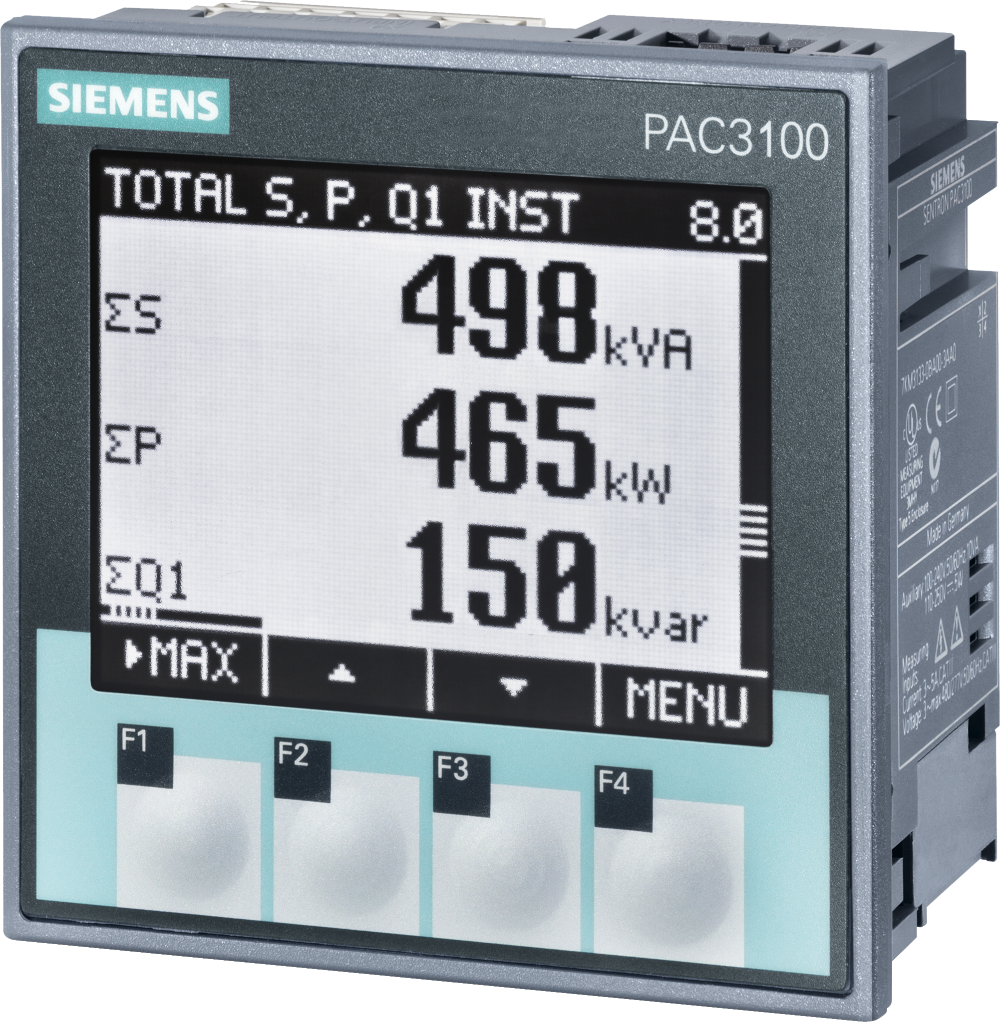
Siemens SENTRON PAC3100
Power and energy meter
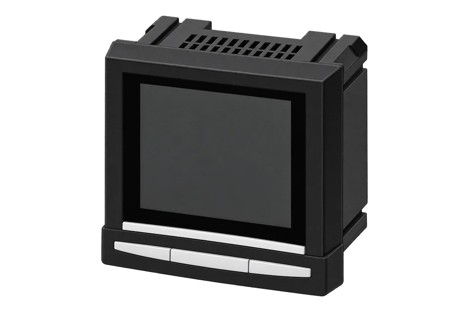
The SENTRON PAC3100 (7KM3133-0BA00-3AA0) is a 96 × 96 mm panel meter for three-phase systems up to 480 V phase to phase, measuring current through external x/5 A current transformers. Its only communication port is an integral RS-485 interface running Modbus RTU. The manual's appendix lists every value by offset, register count and format: instantaneous, maximum and minimum values are 32-bit Float in V, A, W, VA and var from offset 1, and the active and reactive energy counters are 64-bit Double in Wh and varh at offsets 801 and 805. Each counter holds the import, export or balance total chosen in the meter settings, so read that choice before trusting the energy value.
Compatibility
Compatible with EpiSensor Edge over Modbus RTU
The PAC3100 is compatible with EpiSensor Edge over its integral RS-485 Modbus RTU interface, read through a ZMB-31 Modbus Interface or a Gateway serial port. Siemens publishes the measured values with offsets, register counts, formats and units, and lists FC03 and FC04 for reading them.
SENTRON PAC3100, order number 7KM3133-0BA00-3AA0, using appendix A.2 of manual A5E02385159B-03 (02/2015). Site check: read voltage a-n at offset 1 and compare it with the display, then read offset 50025 to learn which energy total offsets 801 and 805 hold. Read-only monitoring: no writes to the settings, the energy counters or the command offsets 60000 to 60009.
Connect it with
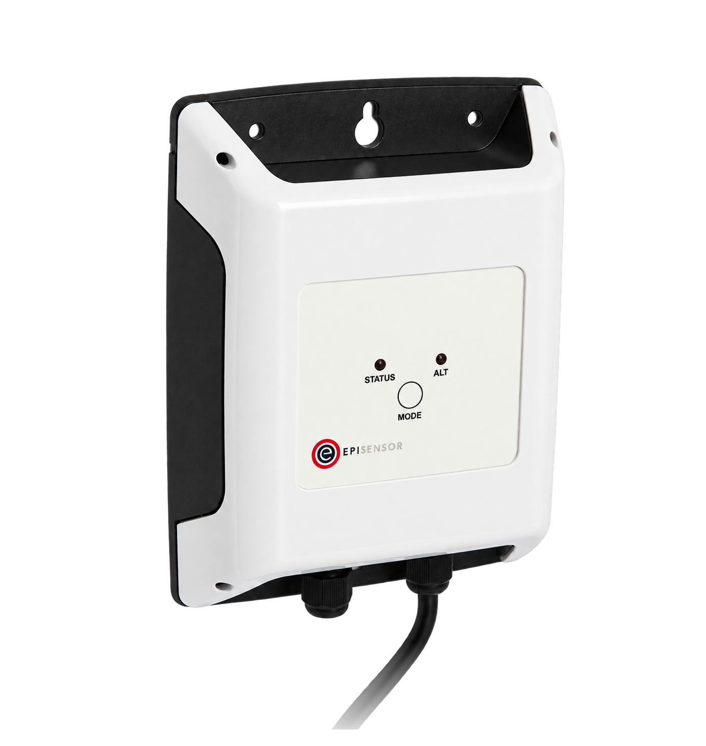
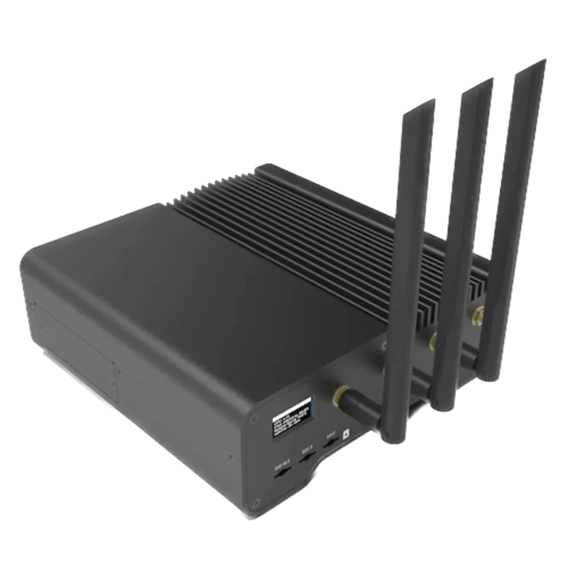
For a meter in a switchboard or panel door where a wireless link avoids running a data cable back to the Gateway
- Modbus
- Wireless
- Edge
- Platforms
When the Gateway sits near the meter, or several meters share one wired RS-485 bus
- Modbus
- Edge
- Platforms
Models
| Models | Interface | Route into Edge |
|---|---|---|
| PAC3100, 7KM3133-0BA00-3AA0 | Integral RS-485 interface running Modbus RTU; wide-range power supply and screw terminals | Read the Float offsets and the Double energy counters with FC03 on the serial path. The manual lists this order number as the only PAC3100 version. |
| PAC3120, PAC3220 | Different meters with their own manual, offsets and interfaces | Not covered by this guide. Use the PAC3120 or PAC3220 guide and its manual rather than this table. |
| PAC3200 | A different PAC meter with its own Modbus documentation | Not covered by this guide. Use the PAC3200 page and its own documentation before adopting any offset from this page. |
Specifications
The PAC3100 is a 96 × 96 mm panel meter for single-phase, two-phase and three-phase measurement in three-wire and four-wire TN, TT and IT systems, connected direct up to 480 V phase to phase or through voltage transformers. It measures true rms values up to the 15th harmonic, derives more than 30 measured variables, keeps maximum and minimum values and counts active and reactive energy for import, export and balance. It has 2 digital inputs, 2 digital outputs and one integral RS-485 Modbus RTU interface.1
- Order number
- 7KM3133-0BA00-3AA0, PAC3100 with wide-range power supply and screw terminals; the only device version the manual lists.1
- Voltage inputs
- 277 V ph-n and 480 V ph-ph AC (+20%), CAT III; higher voltages through voltage transformers. Connection types 3P4W and 3P3W.1
- Current inputs
- x/5 A AC through external current transformers; 10 A continuous, 100 A for 1 s. Not for DC.1
- Accuracy
- IEC 61557-12 class 1 for voltage, current, active and apparent power and active energy; class 3 for reactive power and energy; class 2 for power factor; class 0.1 for frequency. Transformer quality adds to the error.1
- RS-485
- Two-wire line plus Common on screw terminals Com, +/B and -/A; Modbus RTU slave; 4800, 9600, 19200 or 38400 baud; 8N1, 8N2, 8E1 or 8O1; address 1 to 247. Factory settings: address 126, 19200 baud, 8N2, response time automatic.1
- Bus termination
- No internal termination or bias resistors. Terminate the first and last node with an external resistor across A and B, about 300 Ω and not below 60 Ω; the manual recommends bias of 560 Ω pull-up and pull-down from 5 V DC elsewhere on the bus.12
- Supply
- 100 to 240 V AC (45 to 65 Hz) or 110 to 250 V DC, ±10%; 5 W DC or 10 VA AC.1
- Housing
- 96 × 96 × 56 mm, 51 mm overall depth, panel cutout 92 × 92 mm, about 325 g. Front IP65, rear IP20.1
- Environment
- Operating -10 to +55 °C, storage -25 to +70 °C, 95% RH at 25 °C without condensation, up to 2000 m, pollution degree 2, enclosed dry rooms only.1
- Approvals
- CE; UL file E314880; C-Tick.1
Interface
Documented measurements and integration boundaries for SENTRON PAC3100.
- The manual lists every value by offset and register count. This guide sends the offset unchanged as the Modbus PDU address, so voltage a-n at offset 1 goes on the wire as 0x0001. FC03 and FC04 both read the measured values, at most 125 registers per request.
- A read that starts in the second register of a two-register value returns an error, so a client that adds one to the offset fails at once rather than returning a shifted value. Neither the register nor byte order of a Float is stated; confirm it with the voltage read in the worked check.
- Voltage a-n, b-n and c-n at offsets 1, 3 and 5, a-b, b-c and c-a at 7, 9 and 11: Float, V.
- Current a, b and c at 13, 15 and 17, neutral current at 37: Float, A.
- Per phase: apparent power at 19 to 23 in VA, active power at 25 to 29 in W, reactive power (VAR1) at 31 to 35 in var, two registers each. The manual lists active power as import/export and reactive power as positive/negative without saying which sign stands for import. It does say that a current input connected the wrong way round inverts the values and gives them a negative sign, which CURRENT DIREC a, b and c correct per phase without rewiring, so check the sign against the display and a known direction of flow.
- Frequency at 39 (45 to 65 Hz), total apparent power at 47 in VA, total active power at 49 in W, total reactive power (VAR1) at 51 in var and total power factor at 53: Float.
- Maximum values from 55 to 107 and minimum values from 109 to 161 follow the same order and format.
- Active energy at 801 in Wh and reactive energy at 805 in varh: Double, four registers each, overflow at 1.0e+12. Each holds one of import, export or balance (import minus export), as selected under SETTINGS > ENERGY COUNTERS; the factory setting is balance for both.
- Offset 50025, two registers, reports that selection: LOWORD for kWh and HIWORD for kvarh, 0 import, 1 export, 2 balance. The two energy counters are the only two of the six totals that can be read at one time.
- The table also lists Float energy copies at 2803 and 2805 with four registers each, although the offsets are two apart. Use the Double counters at 801 and 805.
- Power demand of the last completed period from 501: cumulated active and reactive power for import and export at 501 to 507, period maximum and minimum active and reactive power at 509 to 515 (Float), period length at 517 and time since the period started at 519 (Unsigned long, s). These values are available only over RS-485, not on the display.
- Device diagnostics and status at 205, digital output and input status at 207 and 209, and parameter change counters at 217 and 219: Unsigned long, two registers each.
- Gaps in a block read are filled with 0xFFFFFFFF, which the manual defines as no measured value. In 3P3W connection the phase-to-neutral voltages, per-phase powers and neutral current are not available.
- The settings from 50001, the communication parameters from 63019, the energy counters at 801 and 805 and the command offsets 60000 to 60009 (factory reset, device reset, min/max reset, energy counter reset) are writable. Keep them all out of a monitoring poll.
Assessment
SENTRON PAC3100, order number 7KM3133-0BA00-3AA0, using appendix A.2 of manual A5E02385159B-03 (02/2015). Site check: read voltage a-n at offset 1 and compare it with the display, then read offset 50025 to learn which energy total offsets 801 and 805 hold. Read-only monitoring: no writes to the settings, the energy counters or the command offsets 60000 to 60009.
- InteroperabilitySupported with conditions
- Siemens documents Modbus RTU on RS-485, the function codes, exception codes, and every value's offset, register count, format and unit. The manual does not state the register order of Float and Double values, so one read compared with the display fixes it.1
- AccuracySupported with conditions
- Class 1 to IEC 61557-12 for voltage, current, active power and active energy, class 3 for reactive values. Only one active and one reactive total (import, export or balance, as configured) can be read at once, and accuracy also depends on the x/5 A CTs and any VTs.1
- SecurityNot yet assessed
- A four-digit password on the front protects the device settings, which stay readable. Settings, communication parameters, energy counters and reset commands are listed as writable over Modbus.1
- ReliabilitySupported with conditions
- Exception codes, a device status register at 205 and the 0xFFFFFFFF no-value marker are documented. Counters are saved every 5 minutes and min/max values every 5 seconds, so a supply loss can cost up to 5 minutes of counted energy.1
- RuggednessSupported with conditions
- Rated -10 to +55 °C, 95% RH at 25 °C without condensation, pollution degree 2 and CAT III. The front is IP65 and the rear IP20, and operation is for enclosed dry rooms, so the meter needs a suitable panel.1
Setup
Read voltage a-n at offset 1, then the energy counter at 801
Appendix A.2.5 of manual A5E02385159B-03 (02/2015) gives voltage a-n at offset 1, two registers, Float in V, readable with FC03 or FC04, and active energy at offset 801, four registers, Double in Wh. The manual calls these numbers offsets and does not state the register order of a Float, so the first read settles both against the meter display. The frames use the factory address 126 (0x7E).
- Request
- 7E 03 00 01 00 02 9E 04: address 126, FC03, PDU address 0x0001 (offset 1, sent unchanged), two registers, RTU CRC.
- Address convention
- If the client adds one and sends PDU address 0x0002 (7E 03 00 02 00 02 6E 04), the read starts in the second register of voltage a-n, and the manual says the meter answers with an error code instead of data.
- Synthetic response
- 7E 03 04 43 66 66 66 2A E5: four data bytes, 43 66 66 66.
- Decode
- With the first register as the upper word, 0x43666666 is the IEEE 754 single-precision value 230.4 V. Keep that order only if the reading agrees with Va-n on the display at the same time.
- Frequency read
- 7E 03 00 27 00 02 7F CF reads offset 39 (0x0027). Synthetic response 7E 03 04 42 47 EB 85 5F CA: 0x4247EB85 = 49.98 Hz.
- Energy read
- 7E 03 03 21 00 04 1F 88 reads four registers at offset 801 (0x0321). Synthetic response 7E 03 08 41 67 8C 29 C0 00 00 00 A2 F2: 0x41678C29C0000000 is the double-precision value 12345678 Wh, or 12345.678 kWh.
- Counter selection
- 7E 03 C3 69 00 02 23 9C reads offset 50025 (0xC369). At the factory setting the synthetic reply 7E 03 04 00 02 00 02 54 F5 holds 2 in both words: both counters report balance, import minus export.
- Acceptance
- Keep the address convention and word order when voltage and frequency agree with the display, and record the counter selection with the device before storing energy.
Acceptance: The response bytes are synthetic decoder checks, not captured meter replies. A real meter must return a voltage and frequency that agree with its display, and a counter selection that matches SETTINGS > ENERGY COUNTERS, before current, power and energy points are enabled.
-
Identify the meter
Check the rating plate for PAC3100 and order number 7KM3133-0BA00-3AA0. Note the connection type (3P4W or 3P3W) and the CT and VT ratios set on the meter, and check them against the installed transformers.
-
Read the serial settings
Under SETTINGS > COMMUNICATION the display shows the address, baud rate, data format and response time. A meter left at the factory settings answers at address 126, 19200 baud, 8N2. Enter the same values in the Edge serial client or the ZMB-31; on a shared bus each meter needs its own address, set on its display.
-
Wire the RS-485 line
Connect +/B, -/A and Com, ground the shield and the Common line as the manual describes, and fit terminating resistors at the first and last node. The PAC3100 has none of its own and no bias resistors.
-
Fix the address convention
Read voltage a-n with FC03 at PDU address 1 for two registers, as in the worked read below, and compare it with the voltage on the display. A client that sends 2 instead starts in the second register of that value and gets an error.
-
Check which energy total is counted
Read offset 50025 for two registers, or look under SETTINGS > ENERGY COUNTERS: 0 is import, 1 export, 2 balance. Label the counters at 801 and 805 to match before you store them, and leave the setting unchanged.
-
Add the points read-only
Add current, power, frequency and power factor as Float, then the energy counters at 801 and 805 as four-register Double in Wh and varh; divide by 1000 for kWh. Never write to the settings, the counters or the command offsets from 60000.
Common questions
- Does the PAC3100 have Modbus TCP?
- No. The manual describes one integral RS-485 interface running Modbus RTU and no Ethernet port. Edge reads it through a ZMB-31 Modbus Interface or a Gateway serial port.1
- Is offset 1 sent as address 1 or 0?
- The manual lists offsets and this guide sends them unchanged: voltage a-n at offset 1 is PDU address 0x0001. Check it with the first read. The manual says a read that starts in the second register of a two-register value returns an error, so a client that adds one to every offset fails straight away.1
- Why does the energy at 801 not match the imported energy?
- The counter at 801 holds the active energy total chosen under SETTINGS > ENERGY COUNTERS: import, export or balance, and balance (import minus export) is the factory setting. Offset 805 does the same for reactive energy. Read offset 50025 to see the choice: 0 import, 1 export, 2 balance.1
- Why did the energy counter go back after a power cut?
- The PAC3100 writes its counters to non-volatile memory every 5 minutes, so after the supply returns the counter can resume from a value up to 5 minutes old. Treat a small step back after an outage as this, not as a meter fault.1
- Why did the meter stop answering after a firmware update?
- Siemens' firmware update instruction says the PAC3100 is set to factory defaults after an update and tells you to write down the device configuration, meter readings and communication settings first. If the meter no longer answers afterwards, try the factory communication settings, address 126, 19200 baud and 8N2, then set the address and CT and VT ratios again on the display.12
- Which wire is A and which is B?
- The PAC3100 terminals are marked Com, +/B and -/A. In Siemens' own firmware update example the meter's +/B goes to terminal A of the USB converter and -/A to its B, because manufacturers label the two wires differently. If the meter never replies, swap the pair before changing any other setting.12
- Why does a value read FF FF FF FF?
- The manual fills gaps in a block read with 0xFFFFFFFF and defines that as no measured value. Values that the connection type cannot measure, such as phase-to-neutral voltage in 3P3W, are also unavailable. Store them as missing, not as a reading.1
- Where are the demand values?
- The power demand of the last completed period is at offsets 501 to 519: cumulated active and reactive power for import and export, period maximum and minimum, period length and time since the period started. It is available only over RS-485 and only during the following period. The period is 1 to 60 minutes, 15 by default.1
Related devices
Sources
- SENTRON 7KM measuring device PAC3100 manual, edition 02/2015, A5E02385159B-03, with the Modbus RTU appendix A.2 (opens in a new tab) (PDF)
- Instruction: firmware update SENTRON PAC3100 (Siemens, 2010, 17 pages), with the RS-485 wiring and the reset to factory defaults (opens in a new tab) (PDF)
Further reading
Product names and trademarks belong to their owners. Publication does not imply endorsement or a commercial relationship.