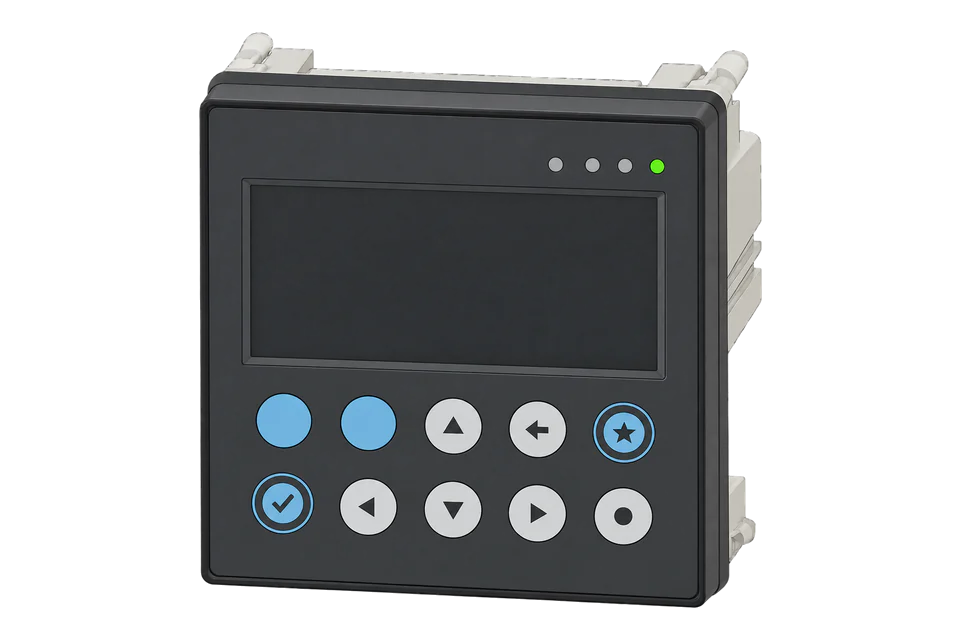
Siemens SENTRON PAC3200
Power monitoring device
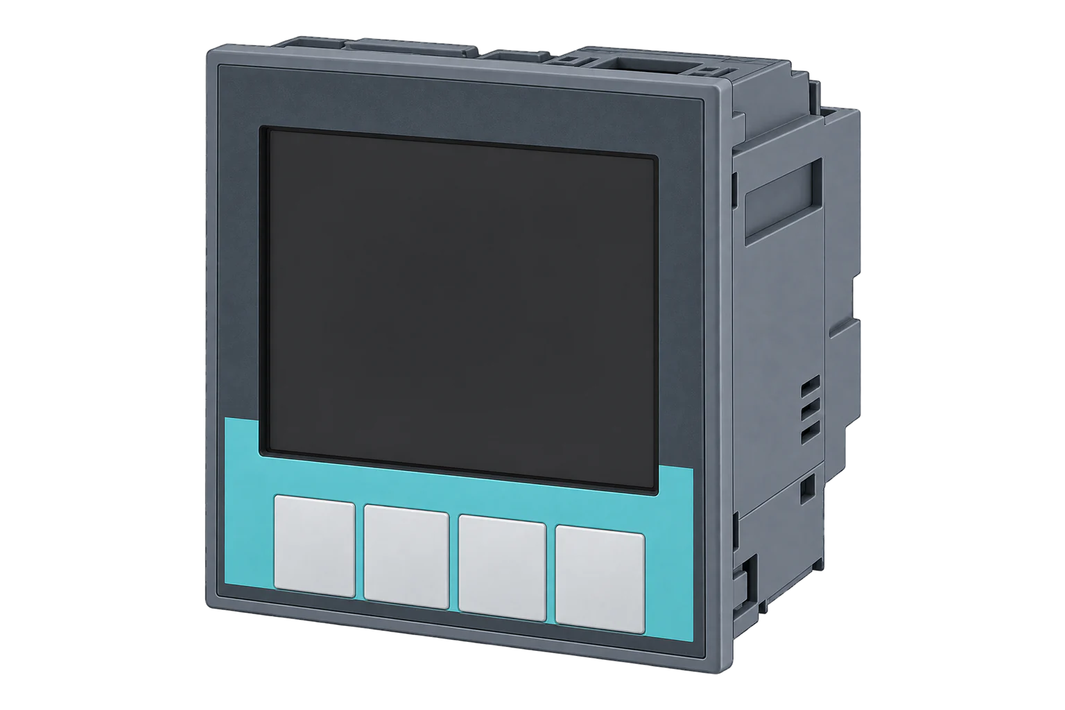
A 96 × 96 mm panel meter for low-voltage distribution, on 1 A or 5 A current transformers, with Class 0.5S active energy and more than 50 measured values. It speaks Modbus TCP on its own Ethernet port, and Modbus RTU through the PAC RS485 expansion module.
Compatibility
Compatible with EpiSensor Edge over Modbus RTU and Modbus TCP.
Connect its RS-485 port to a Modbus Interface or to a serial interface on the Gateway, or use its Ethernet port for Modbus TCP. Edge polls it with its Modbus client.
Edge reads 32 values from it, listed under Interface.
Connect it with
-
Modbus Interface ZMB-3XFrom €399 ex VAT Configure Modbus Interface
-
Gateway ZGW-20From €899 ex VAT Configure Gateway
-
Evaluation Gateway on a Raspberry Pi Edge with one device licensedFree Set up Evaluation Gateway on a Raspberry Pi


Specifications
The SENTRON PAC3200 is Siemens' panel-mounted power monitoring device for low-voltage switchboards. It fits a 96 × 96 mm cutout, 51 mm deep, and measures single-phase, two-phase and three-phase systems with two, three or four wires, in TN, TT and IT networks. The multi-range supply version connects directly to systems up to 690 V between phases; the extra-low voltage version up to 500 V. Current always comes from x/1 A or x/5 A transformers.1
- Power
- Mains. Auxiliary supply on L/+ and N/-: 95 to 240 V AC or 110 to 340 V DC on the multi-range version, 22 to 65 V DC on the extra-low voltage version, typically 8 VA. Do not take it from the voltage transformers.1
- Active energy accuracy
- Class 0.5S (IEC 62053-22)1
- Reactive energy accuracy
- Class 2 (IEC 62053-23)1
- Measuring accuracy
- Voltage ±0.3 %, current ±0.2 %, power ±0.5 %, frequency ±0.05 %1
- Voltage inputs (multi-range supply)
- Up to 400 V L-N and 690 V L-L (+20 %), 347 V and 600 V for UL1
- Voltage inputs (extra-low voltage supply)
- Up to 289 V L-N and 500 V L-L (+20 %)1
- Current inputs
- x/1 A or x/5 A current transformers, 100 A for 1 s1
- Communication
- Ethernet (RJ45) for Modbus TCP or SEAbus TCP; Modbus RTU with the PAC RS485 expansion module1
- Dimensions
- 96 × 96 × 51 mm; 73 mm deep with an expansion module1
- Protection
- IP65 front; IP20 rear with screw terminals, IP10 with ring lugs1
- Operating temperature
- -10 to 55 °C1
- Order numbers
- 7KM2112-0BA00-3AA0 (multi-range supply, screw terminals), 7KM2112-0BA00-2AA0 (ring lugs), 7KM2111-1BA00-3AA0 (extra-low voltage supply)1
Where it is used
Incomers and main feeders in low-voltage switchboards, on existing 1 A or 5 A current transformers.
Transformer and distribution board monitoringEnergy and power quality reporting across the switchboards of several sites, with voltage and current THD per phase.
Multi-site energy monitoringReading meters that are already on a site's Ethernet network into a BMS or SCADA system through Edge.
Modbus meter integration for a BMS or SCADA system
Interface
This register map is for the 7KM2112-0BA00-3AA0 (firmware 2.4.2).
Communication settings
- Ethernet protocol
- Modbus TCP on port 502; the meter ships set to SEAbus TCP
- Network settings
- IP address, subnet and gateway, set on the display
- RS-485
- Modbus RTU with the PAC RS485 expansion module
- Baud rate (RS-485)
- 4800, 9600, 19200 or 38400 bit/s; 19200 by default
- Framing (RS-485)
- 8N2 (default), 8E1, 8O1 or 8N1
- Unit address (RS-485)
- 126 by default
- Response delay (RS-485)
- 0 to 255 ms; 0, the default, is automatic
- Read functions
- FC03 and FC04 on every measured value
- Write function
- FC16, for settings only
- Read with
- FC03 (holding registers)
- Word order
- High word first on every value
- Addresses
- Zero-based PDU addresses, as sent on the bus
From SENTRON PAC3200 Power Monitoring Device manual (A5E01168664B-04, 02/2008)1.
Register map
| Point | Address | Hex | Format | Scale | Unit |
|---|---|---|---|---|---|
| Voltage L1-N | 1 | 0x0001 |
FLOAT32 | ×1 | V |
| Voltage L2-N | 3 | 0x0003 |
FLOAT32 | ×1 | V |
| Voltage L3-N | 5 | 0x0005 |
FLOAT32 | ×1 | V |
| Voltage L1-L2 | 7 | 0x0007 |
FLOAT32 | ×1 | V |
| Voltage L2-L3 | 9 | 0x0009 |
FLOAT32 | ×1 | V |
| Voltage L3-L1 | 11 | 0x000B |
FLOAT32 | ×1 | V |
| Current L1 | 13 | 0x000D |
FLOAT32 | ×1 | A |
| Current L2 | 15 | 0x000F |
FLOAT32 | ×1 | A |
| Current L3 | 17 | 0x0011 |
FLOAT32 | ×1 | A |
| Apparent Power L1 | 19 | 0x0013 |
FLOAT32 | ×1 | VA |
| Apparent Power L2 | 21 | 0x0015 |
FLOAT32 | ×1 | VA |
| Apparent Power L3 | 23 | 0x0017 |
FLOAT32 | ×1 | VA |
| Active Power L1 | 25 | 0x0019 |
FLOAT32 | ×1 | W |
| Active Power L2 | 27 | 0x001B |
FLOAT32 | ×1 | W |
| Active Power L3 | 29 | 0x001D |
FLOAT32 | ×1 | W |
| Reactive Power L1 | 31 | 0x001F |
FLOAT32 | ×1 | var |
| Reactive Power L2 | 33 | 0x0021 |
FLOAT32 | ×1 | var |
| Reactive Power L3 | 35 | 0x0023 |
FLOAT32 | ×1 | var |
| Power Factor L1 | 37 | 0x0025 |
FLOAT32 | ×1 | - |
| Power Factor L2 | 39 | 0x0027 |
FLOAT32 | ×1 | - |
| Power Factor L3 | 41 | 0x0029 |
FLOAT32 | ×1 | - |
| Voltage THD L1 | 43 | 0x002B |
FLOAT32 | ×1 | % |
| Voltage THD L2 | 45 | 0x002D |
FLOAT32 | ×1 | % |
| Voltage THD L3 | 47 | 0x002F |
FLOAT32 | ×1 | % |
| Current THD L1 | 49 | 0x0031 |
FLOAT32 | ×1 | % |
| Current THD L2 | 51 | 0x0033 |
FLOAT32 | ×1 | % |
| Current THD L3 | 53 | 0x0035 |
FLOAT32 | ×1 | % |
| Frequency | 55 | 0x0037 |
FLOAT32 | ×1 | Hz |
| Total Apparent Power | 63 | 0x003F |
FLOAT32 | ×1 | VA |
| Total Active Power | 65 | 0x0041 |
FLOAT32 | ×1 | W |
| Total Reactive Power | 67 | 0x0043 |
FLOAT32 | ×1 | var |
| Total Power Factor | 69 | 0x0045 |
FLOAT32 | ×1 | - |
Siemens lists each value by offset, and the offset is the address sent on the bus: total active power is offset 65, which a 40001-style master shows as 40066. A read must start on the first register of a value, or the meter answers with an error.12
The ten energy counters are 64-bit floating-point values in Wh, varh and VAh at offsets 801 to 837, four registers each. The Edge template leaves them out because Edge has no 64-bit float format; the instantaneous values above are all 32-bit.1
Edge template
This JSON file supplies the register map. Applying it to an existing meter replaces its sensor list while retaining the site connection, unit ID and enable state.
| Model | Connection | Points | Version | Updated | Download |
|---|---|---|---|---|---|
| 7KM2112-0BA00-3AA0 | Modbus RTU over RS-485, Modbus TCP | 32 | 1.0.0 | Download |
Downloads need a signed-in account with Edge download access.
Use the template in Edge
- Import the JSON file
In Edge, open Settings, then Devices and Templates. Choose Import JSON and select the downloaded file. Confirm that the model and template name match your device.
- Load the map for your meter
For a new Modbus device, use Load Template before entering the manufacturer or model; it fills those fields and the register list. Set the name, site connection and unit ID, check the polling enable state, then test before saving. For an existing device, apply only to the matching model; this replaces its sensor list but retains its connection, unit ID and enable state.
- Test a reading
Use Test in the wizard and compare a known reading with the meter display. Check its unit, sign and scale, then confirm that timestamps keep advancing. These starter maps are read-only and leave exports off until you configure them.
Setup
-
Choose the port
Use the built-in Ethernet port for Modbus TCP, or fit a PAC RS485 expansion module for Modbus RTU on an RS-485 bus through a ZMB-31 or the Gateway's serial interface.1
-
Set the network or bus
For Ethernet, enter the IP address, subnet and gateway under Settings > Communication, then change Protocol from SEAbus TCP to MODBUS TCP and restart the meter. For RS-485, set the address, baud rate and framing under Settings > RS485 Module: the module starts at address 126, 19200 bit/s and 8N2.1
-
Point Edge at it
Add the meter to Edge as a Modbus TCP device on port 502, or as an RTU device with the same address, speed and framing as the module.1
-
Read one register
Import the template and read Voltage L1-N at offset 1. It arrives as a float in volts and should match the display.1
-
Enable the map
Once voltage, current and total active power match the display, enable the rest of the map and watch several fresh readings before you add exports or alarms.
Common questions
- Why does the PAC3200 not answer Modbus TCP?
- The Ethernet port ships speaking SEAbus TCP. Enter the network settings, change Protocol to MODBUS TCP under Settings > Communication and restart the meter. Modbus TCP then answers on port 502.1
- Which function codes does the PAC3200 support?
- Every measured value can be read with function code 3 or 4. Writable settings, such as the communication parameters from offset 63015, are written with function code 16.1
- What are the RS-485 settings on the PAC RS485 module?
- 4800, 9600, 19200 or 38400 bit/s, with 8N2, 8E1, 8O1 or 8N1 framing. The module starts at address 126, 19200 bit/s and 8N2, speaking Modbus RTU with an automatic response time.1
Related devices

Sources
- SENTRON PAC3200 Power Monitoring Device manual (A5E01168664B-04, 02/2008) (opens in a new tab) (PDF)
- Data exchange between S7-1200 and SENTRON PAC via Modbus TCP (Set 22) (opens in a new tab) (PDF)
- Siemens SENTRON PAC3200 register map (opens in a new tab)
Further reading
Product names and trademarks belong to their owners. Publication does not imply endorsement or a commercial relationship.