Schneider Electric iEM3000 series
Energy meter
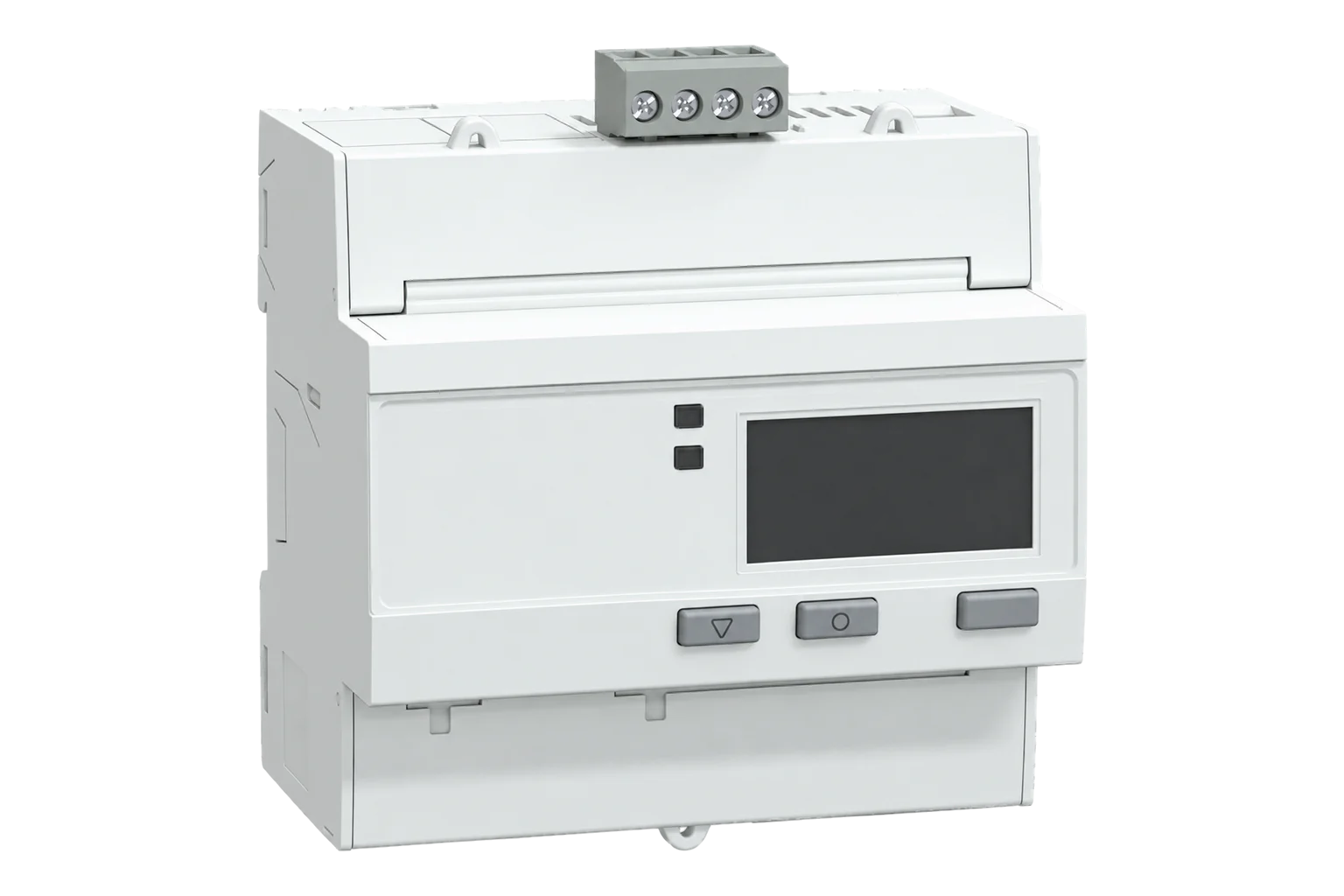
Schneider Electric DIN-rail meters with RS-485 Modbus RTU: iEM3150 and iEM3155 measure directly up to 63 A, iEM3350 and iEM3355 up to 125 A, and iEM3250 and iEM3255 use 1 A or 5 A CTs. The starter templates use Float32 measurements; the full device map also contains integer energy and configuration registers.
Also sold asiEM3150iEM3155iEM3250iEM3255iEM3350iEM3355
Compatibility
Compatible with EpiSensor Edge over Modbus RTU.
Connect its RS-485 port to a Modbus Interface or to a serial interface on the Gateway. Edge polls it with its Modbus client.
Edge reads 23 values from it, listed under Interface.
Connect it with
-
Modbus Interface ZMB-3XFrom €399 ex VAT Configure Modbus Interface
-
Gateway ZGW-20From €899 ex VAT Configure Gateway


Specifications
Every Modbus model measures current, voltage, active power, power factor, frequency and active energy, per phase and in total. The iEM3155, iEM3255 and iEM3355 add reactive and apparent power, export and reactive energy, four tariffs, a digital input, a digital output, an overload alarm and MID approval for billing. The iEM3150, iEM3250 and iEM3350 are the plain versions: Schneider leaves those registers, the tariffs and MID approval out.1
- Power
- Self-powered from the measured supply. The meter runs from its voltage inputs. There is no separate auxiliary supply to wire.1
- Active energy accuracy
- Class 1 (IEC 62053-21); Class 0.5S (IEC 62053-22) on the iEM3250 and iEM3255 with 5 A CTs1
- MID approval
- iEM3155 and iEM3355: Class B (EN 50470-3); iEM3255: Class B with 1 A CTs, Class C with 5 A CTs1
- Direct current range
- 0.5 to 63 A (iEM3150, iEM3155); 1 to 125 A (iEM3350, iEM3355)1
- CT inputs (iEM3250, iEM3255)
- 1 A or 5 A nominal, 20 mA to 6 A measured1
- Voltage
- 100 to 277 V L-N, 173 to 480 V L-L, ±20 %1
- Frequency
- 50 or 60 Hz, ±10 %1
- Tariffs
- 4 on the iEM3155, iEM3255 and iEM3355, switched by internal clock, digital input or Modbus1
- Width
- 5 modules of 18 mm (63 A models); 7 modules (125 A models)1
- Protection
- IP40 front panel, IP20 body1
- Operating conditions
- -25 to 70 °C, 5 to 95 % RH non-condensing1
- Order references
- A9MEM3150, A9MEM3155, A9MEM3250, A9MEM3255, A9MEM3350, A9MEM33553
Where it is used
Tenant and departmental submetering using an appropriately approved iEM3155, iEM3255 or iEM3355 installation; verify the applicable billing requirements.
Tenant submetering and cost allocationFeeder and incomer monitoring on larger boards through current transformers, with the iEM3250 or iEM3255.
Transformer and distribution board monitoringMetering air handling units, chillers and heat pumps on their own circuits, up to 63 A or 125 A direct.
HVAC energy monitoring for commercial buildingsBringing meters already on a Modbus bus into a BMS or SCADA system through Edge.
Modbus meter integration for a BMS or SCADA system
Interface
This register map is for the iEM3150.
Communication settings: iEM3150
- Protocol
- Modbus RTU over RS-485
- Unit address
- 1 to 247
- Baud rate
- 9600, 19200 or 38400 bit/s
- Parity
- Even, odd or none, with 1 stop bit
- Functions
- FC03 read holding registers, FC16 write multiple registers, FC43/14 read device identification
- Terminals
- D0/- (A), D1/+ (B), 0V and shield
- Cable
- Shielded twisted pair, up to 2.5 mm² (14 AWG)
- Port isolation
- 4.0 kV rms
- Settings lock
- With Com. Protection enabled (the factory setting), communication settings change only from the front panel
- Read with
- FC03 (holding registers)
- Word order
- High word first on every value
- Addresses
- Zero-based PDU addresses, as sent on the bus
From Energy meters iEM3100 / iEM3200 / iEM3300 series user manual5.
Register map: iEM3150
| Point | Address | Hex | Format | Scale | Unit |
|---|---|---|---|---|---|
| Current L1 | 2999 | 0x0BB7 |
FLOAT32 | ×1 | A |
| Current L2 | 3001 | 0x0BB9 |
FLOAT32 | ×1 | A |
| Current L3 | 3003 | 0x0BBB |
FLOAT32 | ×1 | A |
| Average Current | 3009 | 0x0BC1 |
FLOAT32 | ×1 | A |
| Voltage L1-L2 | 3019 | 0x0BCB |
FLOAT32 | ×1 | V |
| Voltage L2-L3 | 3021 | 0x0BCD |
FLOAT32 | ×1 | V |
| Voltage L3-L1 | 3023 | 0x0BCF |
FLOAT32 | ×1 | V |
| Average Voltage L-L | 3025 | 0x0BD1 |
FLOAT32 | ×1 | V |
| Voltage L1-N | 3027 | 0x0BD3 |
FLOAT32 | ×1 | V |
| Voltage L2-N | 3029 | 0x0BD5 |
FLOAT32 | ×1 | V |
| Voltage L3-N | 3031 | 0x0BD7 |
FLOAT32 | ×1 | V |
| Average Voltage L-N | 3035 | 0x0BDB |
FLOAT32 | ×1 | V |
| Active Power L1 | 3053 | 0x0BED |
FLOAT32 | ×1 | kW |
| Active Power L2 | 3055 | 0x0BEF |
FLOAT32 | ×1 | kW |
| Active Power L3 | 3057 | 0x0BF1 |
FLOAT32 | ×1 | kW |
| Total Active Power | 3059 | 0x0BF3 |
FLOAT32 | ×1 | kW |
| Total Power Factor | 3083 | 0x0C0B |
FLOAT32 | ×1 | - |
| Frequency | 3109 | 0x0C25 |
FLOAT32 | ×1 | Hz |
| Total Active Energy Import | 45099 | 0xB02B |
FLOAT32 | ×1 | kWh |
| Partial Active Energy Import | 45107 | 0xB033 |
FLOAT32 | ×1 | kWh |
| Active Energy Import L1 | 45111 | 0xB037 |
FLOAT32 | ×1 | kWh |
| Active Energy Import L2 | 45113 | 0xB039 |
FLOAT32 | ×1 | kWh |
| Active Energy Import L3 | 45115 | 0xB03B |
FLOAT32 | ×1 | kWh |
This register map is for the iEM3155.
Communication settings: iEM3155
- Protocol
- Modbus RTU over RS-485
- Unit address
- 1 to 247
- Baud rate
- 9600, 19200 or 38400 bit/s
- Parity
- Even, odd or none, with 1 stop bit
- Functions
- FC03 read holding registers, FC16 write multiple registers, FC43/14 read device identification
- Terminals
- D0/- (A), D1/+ (B), 0V and shield
- Cable
- Shielded twisted pair, up to 2.5 mm² (14 AWG)
- Port isolation
- 4.0 kV rms
- Settings lock
- With Com. Protection enabled (the factory setting), communication settings change only from the front panel
- Read with
- FC03 (holding registers)
- Word order
- High word first on every value
- Addresses
- Zero-based PDU addresses, as sent on the bus
From Energy meters iEM3100 / iEM3200 / iEM3300 series user manual5.
Register map: iEM3155
| Point | Address | Hex | Format | Scale | Unit |
|---|---|---|---|---|---|
| Current L1 | 2999 | 0x0BB7 |
FLOAT32 | ×1 | A |
| Current L2 | 3001 | 0x0BB9 |
FLOAT32 | ×1 | A |
| Current L3 | 3003 | 0x0BBB |
FLOAT32 | ×1 | A |
| Average Current | 3009 | 0x0BC1 |
FLOAT32 | ×1 | A |
| Voltage L1-L2 | 3019 | 0x0BCB |
FLOAT32 | ×1 | V |
| Voltage L2-L3 | 3021 | 0x0BCD |
FLOAT32 | ×1 | V |
| Voltage L3-L1 | 3023 | 0x0BCF |
FLOAT32 | ×1 | V |
| Average Voltage L-L | 3025 | 0x0BD1 |
FLOAT32 | ×1 | V |
| Voltage L1-N | 3027 | 0x0BD3 |
FLOAT32 | ×1 | V |
| Voltage L2-N | 3029 | 0x0BD5 |
FLOAT32 | ×1 | V |
| Voltage L3-N | 3031 | 0x0BD7 |
FLOAT32 | ×1 | V |
| Average Voltage L-N | 3035 | 0x0BDB |
FLOAT32 | ×1 | V |
| Active Power L1 | 3053 | 0x0BED |
FLOAT32 | ×1 | kW |
| Active Power L2 | 3055 | 0x0BEF |
FLOAT32 | ×1 | kW |
| Active Power L3 | 3057 | 0x0BF1 |
FLOAT32 | ×1 | kW |
| Total Active Power | 3059 | 0x0BF3 |
FLOAT32 | ×1 | kW |
| Total Reactive Power | 3067 | 0x0BFB |
FLOAT32 | ×1 | kVAR |
| Total Apparent Power | 3075 | 0x0C03 |
FLOAT32 | ×1 | kVA |
| Total Power Factor | 3083 | 0x0C0B |
FLOAT32 | ×1 | - |
| Frequency | 3109 | 0x0C25 |
FLOAT32 | ×1 | Hz |
| Total Active Energy Import | 45099 | 0xB02B |
FLOAT32 | ×1 | kWh |
| Total Active Energy Export | 45101 | 0xB02D |
FLOAT32 | ×1 | kWh |
| Total Reactive Energy Import | 45103 | 0xB02F |
FLOAT32 | ×1 | kVARh |
| Total Reactive Energy Export | 45105 | 0xB031 |
FLOAT32 | ×1 | kVARh |
| Partial Active Energy Import | 45107 | 0xB033 |
FLOAT32 | ×1 | kWh |
| Partial Reactive Energy Import | 45109 | 0xB035 |
FLOAT32 | ×1 | kVARh |
| Active Energy Import L1 | 45111 | 0xB037 |
FLOAT32 | ×1 | kWh |
| Active Energy Import L2 | 45113 | 0xB039 |
FLOAT32 | ×1 | kWh |
| Active Energy Import L3 | 45115 | 0xB03B |
FLOAT32 | ×1 | kWh |
This register map is for the iEM3250.
Communication settings: iEM3250
- Protocol
- Modbus RTU over RS-485
- Unit address
- 1 to 247
- Baud rate
- 9600, 19200 or 38400 bit/s
- Parity
- Even, odd or none, with 1 stop bit
- Functions
- FC03 read holding registers, FC16 write multiple registers, FC43/14 read device identification
- Terminals
- D0/- (A), D1/+ (B), 0V and shield
- Cable
- Shielded twisted pair, up to 2.5 mm² (14 AWG)
- Port isolation
- 4.0 kV rms
- Settings lock
- With Com. Protection enabled (the factory setting), communication settings change only from the front panel
- Read with
- FC03 (holding registers)
- Word order
- High word first on every value
- Addresses
- Zero-based PDU addresses, as sent on the bus
From Energy meters iEM3100 / iEM3200 / iEM3300 series user manual5.
Register map: iEM3250
| Point | Address | Hex | Format | Scale | Unit |
|---|---|---|---|---|---|
| Current L1 | 2999 | 0x0BB7 |
FLOAT32 | ×1 | A |
| Current L2 | 3001 | 0x0BB9 |
FLOAT32 | ×1 | A |
| Current L3 | 3003 | 0x0BBB |
FLOAT32 | ×1 | A |
| Average Current | 3009 | 0x0BC1 |
FLOAT32 | ×1 | A |
| Voltage L1-L2 | 3019 | 0x0BCB |
FLOAT32 | ×1 | V |
| Voltage L2-L3 | 3021 | 0x0BCD |
FLOAT32 | ×1 | V |
| Voltage L3-L1 | 3023 | 0x0BCF |
FLOAT32 | ×1 | V |
| Average Voltage L-L | 3025 | 0x0BD1 |
FLOAT32 | ×1 | V |
| Voltage L1-N | 3027 | 0x0BD3 |
FLOAT32 | ×1 | V |
| Voltage L2-N | 3029 | 0x0BD5 |
FLOAT32 | ×1 | V |
| Voltage L3-N | 3031 | 0x0BD7 |
FLOAT32 | ×1 | V |
| Average Voltage L-N | 3035 | 0x0BDB |
FLOAT32 | ×1 | V |
| Active Power L1 | 3053 | 0x0BED |
FLOAT32 | ×1 | kW |
| Active Power L2 | 3055 | 0x0BEF |
FLOAT32 | ×1 | kW |
| Active Power L3 | 3057 | 0x0BF1 |
FLOAT32 | ×1 | kW |
| Total Active Power | 3059 | 0x0BF3 |
FLOAT32 | ×1 | kW |
| Total Power Factor | 3083 | 0x0C0B |
FLOAT32 | ×1 | - |
| Frequency | 3109 | 0x0C25 |
FLOAT32 | ×1 | Hz |
| Total Active Energy Import | 45099 | 0xB02B |
FLOAT32 | ×1 | kWh |
| Partial Active Energy Import | 45107 | 0xB033 |
FLOAT32 | ×1 | kWh |
| Active Energy Import L1 | 45111 | 0xB037 |
FLOAT32 | ×1 | kWh |
| Active Energy Import L2 | 45113 | 0xB039 |
FLOAT32 | ×1 | kWh |
| Active Energy Import L3 | 45115 | 0xB03B |
FLOAT32 | ×1 | kWh |
This register map is for the iEM3255.
Communication settings: iEM3255
- Protocol
- Modbus RTU over RS-485
- Unit address
- 1 to 247
- Baud rate
- 9600, 19200 or 38400 bit/s
- Parity
- Even, odd or none, with 1 stop bit
- Functions
- FC03 read holding registers, FC16 write multiple registers, FC43/14 read device identification
- Terminals
- D0/- (A), D1/+ (B), 0V and shield
- Cable
- Shielded twisted pair, up to 2.5 mm² (14 AWG)
- Port isolation
- 4.0 kV rms
- Settings lock
- With Com. Protection enabled (the factory setting), communication settings change only from the front panel
- Read with
- FC03 (holding registers)
- Word order
- High word first on every value
- Addresses
- Zero-based PDU addresses, as sent on the bus
From Energy meters iEM3100 / iEM3200 / iEM3300 series user manual5.
Register map: iEM3255
| Point | Address | Hex | Format | Scale | Unit |
|---|---|---|---|---|---|
| Current L1 | 2999 | 0x0BB7 |
FLOAT32 | ×1 | A |
| Current L2 | 3001 | 0x0BB9 |
FLOAT32 | ×1 | A |
| Current L3 | 3003 | 0x0BBB |
FLOAT32 | ×1 | A |
| Average Current | 3009 | 0x0BC1 |
FLOAT32 | ×1 | A |
| Voltage L1-L2 | 3019 | 0x0BCB |
FLOAT32 | ×1 | V |
| Voltage L2-L3 | 3021 | 0x0BCD |
FLOAT32 | ×1 | V |
| Voltage L3-L1 | 3023 | 0x0BCF |
FLOAT32 | ×1 | V |
| Average Voltage L-L | 3025 | 0x0BD1 |
FLOAT32 | ×1 | V |
| Voltage L1-N | 3027 | 0x0BD3 |
FLOAT32 | ×1 | V |
| Voltage L2-N | 3029 | 0x0BD5 |
FLOAT32 | ×1 | V |
| Voltage L3-N | 3031 | 0x0BD7 |
FLOAT32 | ×1 | V |
| Average Voltage L-N | 3035 | 0x0BDB |
FLOAT32 | ×1 | V |
| Active Power L1 | 3053 | 0x0BED |
FLOAT32 | ×1 | kW |
| Active Power L2 | 3055 | 0x0BEF |
FLOAT32 | ×1 | kW |
| Active Power L3 | 3057 | 0x0BF1 |
FLOAT32 | ×1 | kW |
| Total Active Power | 3059 | 0x0BF3 |
FLOAT32 | ×1 | kW |
| Total Reactive Power | 3067 | 0x0BFB |
FLOAT32 | ×1 | kVAR |
| Total Apparent Power | 3075 | 0x0C03 |
FLOAT32 | ×1 | kVA |
| Total Power Factor | 3083 | 0x0C0B |
FLOAT32 | ×1 | - |
| Frequency | 3109 | 0x0C25 |
FLOAT32 | ×1 | Hz |
| Total Active Energy Import | 45099 | 0xB02B |
FLOAT32 | ×1 | kWh |
| Total Active Energy Export | 45101 | 0xB02D |
FLOAT32 | ×1 | kWh |
| Total Reactive Energy Import | 45103 | 0xB02F |
FLOAT32 | ×1 | kVARh |
| Total Reactive Energy Export | 45105 | 0xB031 |
FLOAT32 | ×1 | kVARh |
| Partial Active Energy Import | 45107 | 0xB033 |
FLOAT32 | ×1 | kWh |
| Partial Reactive Energy Import | 45109 | 0xB035 |
FLOAT32 | ×1 | kVARh |
| Active Energy Import L1 | 45111 | 0xB037 |
FLOAT32 | ×1 | kWh |
| Active Energy Import L2 | 45113 | 0xB039 |
FLOAT32 | ×1 | kWh |
| Active Energy Import L3 | 45115 | 0xB03B |
FLOAT32 | ×1 | kWh |
This register map is for the iEM3350.
Communication settings: iEM3350
- Protocol
- Modbus RTU over RS-485
- Unit address
- 1 to 247
- Baud rate
- 9600, 19200 or 38400 bit/s
- Parity
- Even, odd or none, with 1 stop bit
- Functions
- FC03 read holding registers, FC16 write multiple registers, FC43/14 read device identification
- Terminals
- D0/- (A), D1/+ (B), 0V and shield
- Cable
- Shielded twisted pair, up to 2.5 mm² (14 AWG)
- Port isolation
- 4.0 kV rms
- Settings lock
- With Com. Protection enabled (the factory setting), communication settings change only from the front panel
- Read with
- FC03 (holding registers)
- Word order
- High word first on every value
- Addresses
- Zero-based PDU addresses, as sent on the bus
From Energy meters iEM3100 / iEM3200 / iEM3300 series user manual5.
Register map: iEM3350
| Point | Address | Hex | Format | Scale | Unit |
|---|---|---|---|---|---|
| Current L1 | 2999 | 0x0BB7 |
FLOAT32 | ×1 | A |
| Current L2 | 3001 | 0x0BB9 |
FLOAT32 | ×1 | A |
| Current L3 | 3003 | 0x0BBB |
FLOAT32 | ×1 | A |
| Average Current | 3009 | 0x0BC1 |
FLOAT32 | ×1 | A |
| Voltage L1-L2 | 3019 | 0x0BCB |
FLOAT32 | ×1 | V |
| Voltage L2-L3 | 3021 | 0x0BCD |
FLOAT32 | ×1 | V |
| Voltage L3-L1 | 3023 | 0x0BCF |
FLOAT32 | ×1 | V |
| Average Voltage L-L | 3025 | 0x0BD1 |
FLOAT32 | ×1 | V |
| Voltage L1-N | 3027 | 0x0BD3 |
FLOAT32 | ×1 | V |
| Voltage L2-N | 3029 | 0x0BD5 |
FLOAT32 | ×1 | V |
| Voltage L3-N | 3031 | 0x0BD7 |
FLOAT32 | ×1 | V |
| Average Voltage L-N | 3035 | 0x0BDB |
FLOAT32 | ×1 | V |
| Active Power L1 | 3053 | 0x0BED |
FLOAT32 | ×1 | kW |
| Active Power L2 | 3055 | 0x0BEF |
FLOAT32 | ×1 | kW |
| Active Power L3 | 3057 | 0x0BF1 |
FLOAT32 | ×1 | kW |
| Total Active Power | 3059 | 0x0BF3 |
FLOAT32 | ×1 | kW |
| Total Power Factor | 3083 | 0x0C0B |
FLOAT32 | ×1 | - |
| Frequency | 3109 | 0x0C25 |
FLOAT32 | ×1 | Hz |
| Total Active Energy Import | 45099 | 0xB02B |
FLOAT32 | ×1 | kWh |
| Partial Active Energy Import | 45107 | 0xB033 |
FLOAT32 | ×1 | kWh |
| Active Energy Import L1 | 45111 | 0xB037 |
FLOAT32 | ×1 | kWh |
| Active Energy Import L2 | 45113 | 0xB039 |
FLOAT32 | ×1 | kWh |
| Active Energy Import L3 | 45115 | 0xB03B |
FLOAT32 | ×1 | kWh |
This register map is for the iEM3355.
Communication settings: iEM3355
- Protocol
- Modbus RTU over RS-485
- Unit address
- 1 to 247
- Baud rate
- 9600, 19200 or 38400 bit/s
- Parity
- Even, odd or none, with 1 stop bit
- Functions
- FC03 read holding registers, FC16 write multiple registers, FC43/14 read device identification
- Terminals
- D0/- (A), D1/+ (B), 0V and shield
- Cable
- Shielded twisted pair, up to 2.5 mm² (14 AWG)
- Port isolation
- 4.0 kV rms
- Settings lock
- With Com. Protection enabled (the factory setting), communication settings change only from the front panel
- Read with
- FC03 (holding registers)
- Word order
- High word first on every value
- Addresses
- Zero-based PDU addresses, as sent on the bus
From Energy meters iEM3100 / iEM3200 / iEM3300 series user manual5.
Register map: iEM3355
| Point | Address | Hex | Format | Scale | Unit |
|---|---|---|---|---|---|
| Current L1 | 2999 | 0x0BB7 |
FLOAT32 | ×1 | A |
| Current L2 | 3001 | 0x0BB9 |
FLOAT32 | ×1 | A |
| Current L3 | 3003 | 0x0BBB |
FLOAT32 | ×1 | A |
| Average Current | 3009 | 0x0BC1 |
FLOAT32 | ×1 | A |
| Voltage L1-L2 | 3019 | 0x0BCB |
FLOAT32 | ×1 | V |
| Voltage L2-L3 | 3021 | 0x0BCD |
FLOAT32 | ×1 | V |
| Voltage L3-L1 | 3023 | 0x0BCF |
FLOAT32 | ×1 | V |
| Average Voltage L-L | 3025 | 0x0BD1 |
FLOAT32 | ×1 | V |
| Voltage L1-N | 3027 | 0x0BD3 |
FLOAT32 | ×1 | V |
| Voltage L2-N | 3029 | 0x0BD5 |
FLOAT32 | ×1 | V |
| Voltage L3-N | 3031 | 0x0BD7 |
FLOAT32 | ×1 | V |
| Average Voltage L-N | 3035 | 0x0BDB |
FLOAT32 | ×1 | V |
| Active Power L1 | 3053 | 0x0BED |
FLOAT32 | ×1 | kW |
| Active Power L2 | 3055 | 0x0BEF |
FLOAT32 | ×1 | kW |
| Active Power L3 | 3057 | 0x0BF1 |
FLOAT32 | ×1 | kW |
| Total Active Power | 3059 | 0x0BF3 |
FLOAT32 | ×1 | kW |
| Total Reactive Power | 3067 | 0x0BFB |
FLOAT32 | ×1 | kVAR |
| Total Apparent Power | 3075 | 0x0C03 |
FLOAT32 | ×1 | kVA |
| Total Power Factor | 3083 | 0x0C0B |
FLOAT32 | ×1 | - |
| Frequency | 3109 | 0x0C25 |
FLOAT32 | ×1 | Hz |
| Total Active Energy Import | 45099 | 0xB02B |
FLOAT32 | ×1 | kWh |
| Total Active Energy Export | 45101 | 0xB02D |
FLOAT32 | ×1 | kWh |
| Total Reactive Energy Import | 45103 | 0xB02F |
FLOAT32 | ×1 | kVARh |
| Total Reactive Energy Export | 45105 | 0xB031 |
FLOAT32 | ×1 | kVARh |
| Partial Active Energy Import | 45107 | 0xB033 |
FLOAT32 | ×1 | kWh |
| Partial Reactive Energy Import | 45109 | 0xB035 |
FLOAT32 | ×1 | kVARh |
| Active Energy Import L1 | 45111 | 0xB037 |
FLOAT32 | ×1 | kWh |
| Active Energy Import L2 | 45113 | 0xB039 |
FLOAT32 | ×1 | kWh |
| Active Energy Import L3 | 45115 | 0xB03B |
FLOAT32 | ×1 | kWh |
Schneider's manual gives each register a hexadecimal address and a decimal register number one higher. The addresses on this page are the ones sent on the bus: register 3000 in the manual, current L1, is address 2999 (0x0BB7).1
Energy is also available as 64-bit integers in watt-hours from register 3204. The maps use the Float32 copies in kilowatt-hours from register 45100, which hold the same totals.1
The iEM3150, iEM3250 and iEM3350 do not answer reactive power, apparent power, export energy or reactive energy. Use the template for the exact model so Edge never polls a register the meter does not have.1
Register 3204 is a four-register 64-bit energy counter in Wh at PDU address 3203 (0x0C83). The starter template instead uses the two-register Float32 copy in kWh at register 45100, PDU 45099 (0xB02B). These encodings and units are different; keep the full integer precision if implementing the 64-bit read.1
The legacy total power-factor register 3084 encodes quadrant information across a range extending beyond -1 to +1. It is not always a conventional signed power factor. The current manual also defines IEC and lead/lag alternatives, so preserve the chosen register’s convention instead of clipping or rescaling a valid value.1
Edge templates
This JSON file supplies the register map. Applying it to an existing meter replaces its sensor list while retaining the site connection, unit ID and enable state.
| Model | Connection | Points | Version | Updated | Download |
|---|---|---|---|---|---|
| iEM3150 | Modbus RTU over RS-485 | 23 | 1.0.0 | Download | |
| iEM3155 | Modbus RTU over RS-485 | 29 | 1.0.0 | Download | |
| iEM3250 | Modbus RTU over RS-485 | 23 | 1.0.0 | Download | |
| iEM3255 | Modbus RTU over RS-485 | 29 | 1.0.0 | Download | |
| iEM3350 | Modbus RTU over RS-485 | 23 | 1.0.0 | Download | |
| iEM3355 | Modbus RTU over RS-485 | 29 | 1.0.0 | Download |
Downloads need a signed-in account with Edge download access.
Use the template in Edge
- Import the JSON file
In Edge, open Settings, then Devices and Templates. Choose Import JSON and select the downloaded file. Confirm that the model and template name match your device.
- Load the map for your meter
For a new Modbus device, use Load Template before entering the manufacturer or model; it fills those fields and the register list. Set the name, site connection and unit ID, check the polling enable state, then test before saving. For an existing device, apply only to the matching model; this replaces its sensor list but retains its connection, unit ID and enable state.
- Test a reading
Use Test in the wizard and compare a known reading with the meter display. Check its unit, sign and scale, then confirm that timestamps keep advancing. These starter maps are read-only and leave exports off until you configure them.
Setup
-
Check the model
This page covers iEM3150, iEM3155, iEM3250, iEM3255, iEM3350 and iEM3355 with RS-485 Modbus. Read the full order reference from the label. Nearby suffixes such as iEM3135, iEM3235 and iEM3335 use M-Bus; do not infer an interface from the iEM3000 family name.1
-
Wire the bus
Use shielded twisted pair and the meter’s D0/- and D1/+ signal markings, with the documented common connection. Match signal polarity to the chosen serial interface’s manual: A/B names alone are not consistent across manufacturers. Follow the meter’s termination and conductor requirements.1
-
Set address and speed
Hold the two setup buttons together for about 2 seconds and enter the password (0010 from the factory). Under Communication, give the meter a unique address from 1 to 247 and set the baud rate and parity. Set Edge to match, with one stop bit.1
-
Read one register
Import the template for the exact model. Read FC03 address 3027 (0x0BD3), quantity 2, for Voltage L1-N: register 3028 in the manual. It is Float32 in V. A synthetic high-word-first payload 43 66 00 00 decodes to 230.0 V; accept the real reading only when it agrees with the simultaneous display.1
-
Enable the map
Once voltage, current and total active power match the display, enable the rest of the map and watch several fresh readings before you add exports or alarms.
Common questions
- Which iEM3000 meters have Modbus?
- The templates on this page cover iEM3150, iEM3155, iEM3250, iEM3255, iEM3350 and iEM3355. Match their exact A9MEM order references. Other suffixes and newer series require their own documented interface and register scope.13
- What is the difference between the iEM3150 and the iEM3155?
- Both measure up to 63 A directly and speak Modbus. The iEM3155 adds MID approval, four-quadrant energy with reactive and apparent power, four tariffs, one digital input, one digital output and an overload alarm. The iEM3150 has none of those, so it answers fewer registers.12
- Why are the addresses one lower than in the Schneider manual?
- The manual lists a register number and an address for every value, and the register number is the address plus one. The address is what goes on the bus. This page and the Edge templates use the address, so register 3000 in the manual is 2999 here.1
- Do I need to swap words on the iEM3000?
- The supplied Float32 templates use high word first without byte or word swapping. Verify voltage against the display before enabling the full map. This template choice is not a statement that every register is Float32: the meter also exposes integer counters and configuration values with different lengths and units.14
- Can the iEM3155 be used for billing?
- The manual describes MID installation conditions for iEM3155, iEM3255 and iEM3355, including a cabinet rated IP51 or better and the stated wiring configurations. Confirm the exact meter approval, installation and applicable billing requirements. A successful Modbus read alone does not establish suitability for tenant billing.1
- Why can I not change the address over Modbus?
- The Com. Protection setting is enabled from the factory. While it is on, communication settings, wiring, date and time and the tariffs can only be changed from the front panel.1
- Should I choose iEM3155 or iEM3255?
- iEM3155 measures the circuit current directly up to 63 A. iEM3255 measures through external 1 A or 5 A CTs, with CT ratio and phase association part of commissioning. The similar communication map does not make their measurement inputs interchangeable.1
- Why is register 3084 returning a power factor above 1?
- The manual’s total power-factor register carries quadrant information in a value that can extend outside -1 to +1. Inspect its documented convention before treating the result as an error. The IEC and lead/lag alternatives use separate registers and require an intentional client mapping.1
Related devices

Sources
- iEM3100 / iEM3200 / iEM3300 series user manual (DOCA0005EN-16) (opens in a new tab) (PDF)
- iEM3155 energy meter, 63 A, Modbus, MID (A9MEM3155) (opens in a new tab)
- Acti9 Isobar P and Active Safety System catalogue 2022 (SE12183), DIN-rail energy meters (opens in a new tab) (PDF)
- mbmd iEM3000 RS-485 driver (opens in a new tab)
- Energy meters iEM3100 / iEM3200 / iEM3300 series user manual (opens in a new tab)
- Current, voltage, power, power factor and frequency register table (opens in a new tab)
- Energy, energy by tariff and input metering register table (opens in a new tab)
- Schneider Electric iEM3000 series device template (opens in a new tab)
Further reading
Product names and trademarks belong to their owners. Publication does not imply endorsement or a commercial relationship.