Selec MFM383A-C
Power and energy meter
The MFM383A is Selec's 96 × 96 mm LCD multifunction meter for three-phase four-wire, three-phase three-wire and single-phase circuits, measuring through external CTs with 1 A or 5 A secondaries. The MFM383A-C and the MFM383A-C-CE, the CE-marked version for Europe, add an RS-485 port running Modbus RTU; the plain MFM383A has none. Every measurement in Selec's register list is a two-register 32-bit float, from phase voltage at 30000 to the total kWh, kVAh and kVArh counters, with the most significant register first by default. Selec numbers the list from 30000, so 30000 is the first register, PDU address 0x0000.

Compatibility
Compatible with EpiSensor Edge over Modbus RTU
The MFM383A-C is compatible with EpiSensor Edge over its RS-485 Modbus RTU port, read through a ZMB-31 Modbus Interface or a Gateway serial port. Selec publishes the input register list with addresses, register lengths, the float data type and the selectable word order with its factory setting.
MFM383A-C and MFM383A-C-CE meters, using the Modbus register addresses list in the MFM383A series operating instructions OP623-V03; the plain MFM383A has no RS-485 port. Site check: read phase 1 voltage at 30000 (PDU address 0x0000) with FC04 and compare it with the display before adding points. Read-only monitoring: no writes to the 40000 setting, reset or endianness registers.
Connect it with
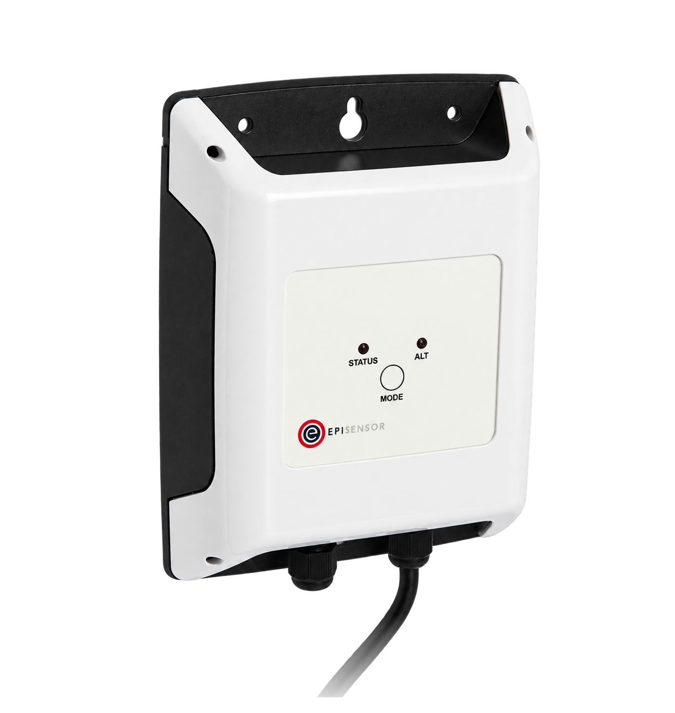
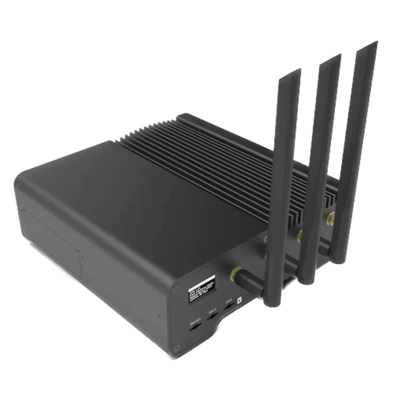
For a meter in a panel where a wireless link avoids running a data cable back to the Gateway
- Modbus
- Wireless
- Edge
- Platforms
When the Gateway sits near the meter, or several meters share one wired RS-485 bus
- Modbus
- Edge
- Platforms
Models
| Models | Interface | Route into Edge |
|---|---|---|
| MFM383A-C | RS-485 Modbus RTU on the + and - terminals beside the pulse output; three CT inputs for 1 A or 5 A secondaries; one energy pulse output | Read the 30000-series float registers with FC04 on the serial path. |
| MFM383A-C-CE | The same RS-485 port, inputs and register list; the CE-marked version for Europe, and the only version the order code tables in the manual and datasheet mark with CE | Same read path and register list as the MFM383A-C. |
| MFM383A | Pulse output only; the manual marks the RS-485 terminals and the serial settings as valid for the communication model only | No Modbus port, so this register list does not apply. Check the order code on the label before planning a Modbus read. |
Specifications
The MFM383A series is a 96 × 96 mm panel-mounted multifunction meter with a backlit LCD of three 4-digit lines and a 7½-digit energy line. It measures true RMS voltage and current, frequency, power factor, active, reactive and apparent power per phase and in total, and total active, reactive and apparent energy, through external CTs and optional PTs. The communication versions add RS-485 with Modbus RTU; every version has one energy pulse output.12
- Versions
- MFM383A without communication; MFM383A-C with RS-485 Modbus RTU; MFM383A-C-CE, the CE-marked version for Europe, with the same RS-485 Modbus RTU port. The manual's order code table marks only the MFM383A-C-CE with CE, the datasheet's table lists the MFM383A and MFM383A-C-CE, and neither lists a UL listing.12
- Voltage inputs
- 11 to 300 V AC line to neutral, 19 to 519 V AC line to line, 45 to 65 Hz, installation category III (600 V). PT primary 100 to 10,000 V and PT secondary 100 to 500 V AC, both programmable.1
- Current inputs
- Nominal 5 A AC, minimum 11 mA, maximum 6 A; burden 0.5 VA at 5 A per phase. CT secondary 1 A or 5 A; CT primary up to 10,000 A, programmable.1
- Wiring
- Three-phase four-wire with 3 CTs, three-phase three-wire with 2 CTs, each with or without PTs, and single-phase two-wire with 1 CT. Single-phase uses the 3P4W network setting.1
- Accuracy
- Voltage and current ±0.5% of full scale; frequency ±0.1%; active, apparent and reactive power 1%; power factor ±0.01; active, reactive and apparent energy class 1. The manual names no accuracy standard.12
- Auxiliary supply
- The operating instructions give 100 to 240 V AC, -15% +12%, 50/60 Hz; the datasheet gives 85 to 270 V AC/DC. Power consumption under 8 VA. Check the label of the installed meter.12
- RS-485
- Modbus RTU, half duplex, on terminals marked + and - (MFM383A-C only). Slave ID 1 to 255; 300, 600, 1200, 2400, 4800, 9600 or 19200 bit/s; parity none, odd or even; 1 or 2 stop bits; 500 m maximum. Factory settings: slave ID 1, 9600 bit/s, no parity, 1 stop bit.1
- Response time
- 100 ms maximum, independent of baud rate.2
- Pulse output
- One energy pulse output, external 24 V DC maximum, 100 mA maximum, pulse width 100 ms ±5 ms. Energy resolution 0.1k or 1k depending on CT ratio × PT ratio.12
- Housing
- Panel mounting, 99 × 99 mm bezel, 50 mm behind a 5 mm bezel, panel cut-out 91.5 × 91.5 mm; 344 g for the MFM383A-C. Protection class II. Terminal torque 0.68 to 0.79 N·m for 0.5 to 2.5 mm² conductors.1
- Environment
- Indoor use, operating -10 to +55 °C, storage -20 to +75 °C, up to 85% RH non-condensing, altitude up to 2000 m, pollution degree II.1
- EMC
- Product standard IEC 61326-1, with immunity to IEC 61000-4-2, -4-3, -4-4, -4-5, -4-6 and -4-11 at the levels in the datasheet, and CISPR 11 emissions. Energy memory retention 10 years.2
Interface
Documented measurements and integration boundaries for MFM383A-C.
- Selec numbers the register list from 30000: 30000 is hexadecimal 0x00, the first input register, so the five-digit address is 30000 plus the zero-based PDU address. Send 0x0000 for phase 1 voltage. A client that numbers registers from one shows the same register as 30001.
- Every value in the readable list is two registers holding a 32-bit float. The factory word order is MSRF, most significant register first (byte order A-B-C-D); LSRF (C-D-A-B) can be selected on configuration page 15 or in holding register 40070. Set the word order in Edge to match the meter rather than changing the meter.
- The manual prints no function code numbers. It lists the measurements as input registers in the 30000 series and titles its example "read data from input register", which a Modbus master reads with FC04; the settings are holding registers in the 40000 series.
- Phase voltages V1N, V2N and V3N at 0x00, 0x02 and 0x04 (30000, 30002, 30004), average line-to-neutral voltage at 0x06. Line voltages V12, V23 and V31 at 0x08, 0x0A and 0x0C, average line-to-line voltage at 0x0E. The table names no unit for voltage, current or frequency; compare one read with the display.
- Currents I1, I2 and I3 at 0x10, 0x12 and 0x14 (30016 to 30020), average current at 0x16.
- Active power kW1, kW2 and kW3 at 0x18, 0x1A and 0x1C; apparent power kVA1 to kVA3 at 0x1E, 0x20 and 0x22; reactive power kVAr1 to kVAr3 at 0x24, 0x26 and 0x28. Totals: kW at 0x2A (30042), kVA at 0x2C and kVAr at 0x2E.
- Power factor PF1, PF2 and PF3 at 0x30, 0x32 and 0x34, average power factor at 0x36, frequency at 0x38 (30056). The manual does not state the sign convention for power factor.
- Energy: kWh at 0x3A (30058), kVAh at 0x3C (30060) and kVArh at 0x3E (30062), as floats in kWh, kVAh and kVArh; the manual's example encodes 1234.12 kWh as 0x449A43D7. There is one total counter for each, with no separate import and export registers.
- A 32-bit float carries about seven significant digits, so the energy counters lose resolution as they grow: from 8,388,608 kWh upwards a float can only change in whole kWh.
- The serial number is at 0x40 (30064), two registers in hexadecimal rather than a float.
- The page 4 example reads total active energy from start address 30090, which is not in the MFM383A-C register list; read the energy counter at 30058 from the page 3 table and use the example only for its byte order.
- Settings are readable and writable holding registers: password at 40000 (0x00), network at 40001, CT secondary and primary at 40002 and 40003, PT secondary at 40004, PT primary at 40005 (two registers), slave ID at 40007, baud rate at 40008, parity at 40009, stop bit at 40010, factory default at 40011, energy resets at 40012 to 40014 and endianness at 40070. Keep all of them out of a monitoring poll.
Assessment
MFM383A-C and MFM383A-C-CE meters, using the Modbus register addresses list in the MFM383A series operating instructions OP623-V03; the plain MFM383A has no RS-485 port. Site check: read phase 1 voltage at 30000 (PDU address 0x0000) with FC04 and compare it with the display before adding points. Read-only monitoring: no writes to the 40000 setting, reset or endianness registers.
- InteroperabilitySupported with conditions
- Selec documents Modbus RTU on RS-485 with a register list that gives the address, hex address, length, float data type and the factory word order, and an example of the byte order. The manual prints no function code numbers or units for voltage, current and frequency, and its example uses an address that is not in the list, so the first read needs one comparison with the display.1
- AccuracySupported with conditions
- Class 1 active, reactive and apparent energy, ±0.5% of full scale voltage and current, and per-phase power and power factor. The energy counters are totals without an import and export split, there are no harmonic or demand registers, and system accuracy also depends on the external CTs and the ratios programmed on the meter.12
- SecurityNot yet assessed
- A four-digit password protects the configuration menu, but the password itself is listed at 40000 as a readable and writable register, alongside the CT, PT, slave ID, baud, factory default and energy reset registers.1
- ReliabilitySupported with conditions
- The datasheet lists immunity tests to the IEC 61000-4 series under IEC 61326-1, a 100 ms maximum response time and 10 years of energy memory retention. The two documents give different auxiliary supply ranges, and neither gives exception codes, so treat failed reads as missing data.12
- RuggednessSupported with conditions
- Rated for indoor use at -10 to +55 °C and up to 85% RH non-condensing, protection class II and installation category III. Neither document gives an IP rating for the front or the terminals, so the meter belongs in a closed panel.1
- ScalabilitySupported with conditions
- Slave IDs 1 to 255 (Modbus unicast uses 1 to 247), up to 19200 bit/s and 500 m of bus. The manual does not state how many meters one segment carries, and each value is a separate two-register float, so the poll list and bus loading set the practical limit.1
- LifecycleNot yet assessed
- The operating instructions carry the revision OP623-V03 and the display shows an 8-digit serial number, but no firmware version or support period is published.1
Setup
Read phase 1 voltage from 30000, PDU address 0x0000
MFM383A series operating instructions OP623-V03, page 3, lists Voltage V1N at address 30000, hex address 0x00, among the readable parameters of length 2 registers with data structure float. Use that list as the starting point and compare the result with the display.
- Request
- 01 04 00 00 00 02 71 CB: slave ID 1, FC04, address 0x0000, two registers, RTU CRC.
- Address convention
- Selec's 30000 is hex 0x00, the zero-based PDU address, so send 0x0000. A client that numbers input registers from one shows the same register as 30001. Do not send 30000 or 0x7530 as the address.
- Synthetic response
- 01 04 04 43 67 66 66 F4 55: four data bytes, first register 43 67, second register 66 66.
- Decode
- Most significant register first (the factory MSRF setting): 0x43676666 as an IEEE 754 32-bit float is 231.4. If the meter is set to LSRF and the client is not, the same bytes read as 0x66664367, about 2.7 × 10²³, which shows at once that the word order is wrong.
- Acceptance
- Keep the point when it agrees with phase 1 voltage on the meter display at the same time. If it does not, check the slave ID, whether the client has added one to the address, and the endianness setting before adding more points.
Acceptance: The response bytes are a synthetic decoder check, not a captured meter reply. A real reply must agree with the display before current, power and energy points are enabled.
-
Identify the meter
Read the order code on the label: MFM383A-C or MFM383A-C-CE has the RS-485 port, the plain MFM383A does not. Confirm the network setting (3P4W or 3P3W) and the CT and PT ratios programmed on the meter with the installer.
-
Read the serial settings on the meter
Configuration pages 8 to 11 hold the slave ID, baud rate, parity and stop bits, and page 15 the endianness (factory MSRF). Enter the same values in the Edge serial client or the ZMB-31 and leave the meter's own settings unchanged.
-
Wire the RS-485 pair
Connect the bus to the terminals marked + and - under RS485, keep the same polarity on every meter, and fit a 120 Ω terminating resistor at the end of the bus as Selec's communication diagram shows. Give each meter its own slave ID within 1 to 247 and keep the bus under 500 m.
-
Make one voltage read
Send FC04 to address 0x0000 for two registers, as in the worked read below, and decode a 32-bit float with the most significant register first. Compare it with phase 1 voltage on the display.
-
Add the points you need
Add current, power, power factor, frequency and the kWh, kVAh and kVArh counters from the page 3 list, each two registers on an even address. Check one power value against the display, and keep the 40000-series setting and reset registers out of the polling configuration.
Common questions
- Is 30000 the address I send?
- No. In Selec's list 30000 is hex address 0x00, so the PDU address on the wire is 0x0000. Selec counts from 30000 where many tools count from 30001, so a client that asks for one-based register numbers needs 30001 for phase 1 voltage. Because every value is two registers on an even address, an address one out returns half of one float and half of the next, which never matches the display.1
- Which function code reads the MFM383A-C?
- The manual prints no function code numbers. It lists the measurements as input registers in the 30000 series and titles its example "read data from input register", which is FC04. The settings are 40000-series holding registers. Confirm FC04 with the first voltage read.1
- What word order does the MFM383A-C use?
- The factory setting is MSRF, most significant register first, which the manual's example calls big endian, byte order A-B-C-D. The meter can be switched to LSRF (C-D-A-B) on configuration page 15 or in register 40070. Set the word order in Edge to match whatever the meter shows rather than changing the meter.1
- Why does the manual's energy example use 30090?
- The page 4 example reads total active energy from start address 30090, but the MFM383A-C register list has kWh at 30058 (0x3A) and nothing at 30090. Use the page 3 table for the address and the example only for how the four bytes of 1234.12 kWh (0x449A43D7) are ordered.1
- Does the MFM383A-C separate import and export energy?
- No. The register list has one kWh, one kVAh and one kVArh counter, all totals, and the manual does not say how reverse power flow is counted. For a circuit that can export, such as one with solar generation, choose a meter with separate import and export registers.1
Related devices
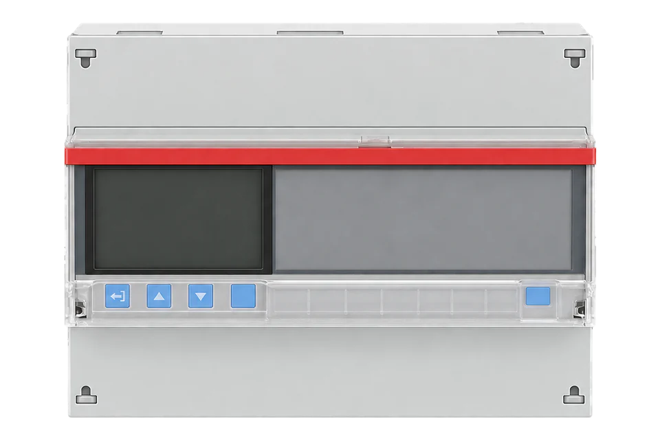
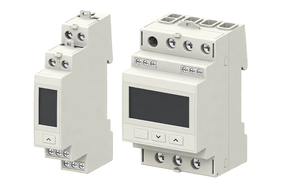


Sources
- MFM383A series operating instructions OP623-V03, with serial communication settings, the Modbus register addresses list (page 3) and the input register byte-order example (page 4) (opens in a new tab)
- MFM383A multifunction meter datasheet, with output, communication, supply, EMC compliance and ordering information (opens in a new tab)
Further reading
- GuideCircutor CVM-C10: another 96 × 96 mm panel meter for external CTs
- GuideEastron SDM630MCT: float registers read with FC04 from address 0
- ToolModbus register address translator
- ToolModbus data decoder
- GuideModbus commissioning over RS-485
- ToolRS-485 termination and bias
- ProtocolModbus devices and register maps
- CategoryEnergy meters
Product names and trademarks belong to their owners. Publication does not imply endorsement or a commercial relationship.