Eastron SDM630-Modbus
Three-phase energy meter
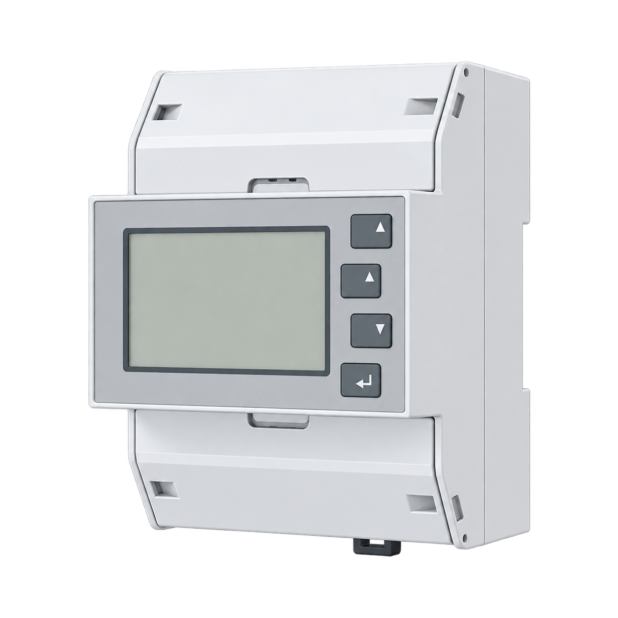
The SDM630-Modbus V2 is a direct-connected three-phase meter with an RS-485 Modbus RTU port and two pulse outputs. Edge reads its measurements through a ZMB-31 or a serial interface on the Gateway.
Compatibility
Compatible through Modbus RTU
Eastron publishes a Modbus RTU protocol document for the SDM630-Modbus V2, an RS-485 meter. Edge reads its measurements over that serial link.
This page covers the direct-connected SDM630-Modbus V2 over RS-485. The SDM630-TCP, SDM630-Mbus, pulse-only, dual-tariff and SDM630MCT versions are separate products with their own interfaces, wiring and register maps.
Connect it with
-
Modbus Interface ZMB-3XFrom €399 ex VAT Configure Modbus Interface
-
Gateway ZGW-20From €899 ex VAT Configure Gateway


For a remote meter where a wireless bridge avoids a new long data-cable route
- Modbus
- Wireless
- Edge
- Platforms
When the Gateway has an isolated RS-485 serial interface
- Modbus
- Edge
- Platforms
Specifications
A direct-connected DIN-rail meter: the load current passes through the meter, up to 100 A per phase, so no current transformers are needed. It measures voltage, current, power, power factor, frequency and energy on all three phases and totals.12
Interface
This register map is for the SDM630-Modbus V2. SDM630-TCP, SDM630-Mbus and SDM630MCT have their own interfaces and are not covered here.
Communication settings
- Interface
- RS-485 Modbus RTU, two pulse outputs, direct connection up to 100 A
- Read with
- FC04 (input registers)
- Word order
- High word first on every value
- Addresses
- Zero-based PDU addresses, as sent on the bus
- Route into Edge
- ZMB-31 wireless bridge or an approved direct serial interface
From SDM630Modbus Smart Meter Modbus Protocol Implementation V1.83.
Register map
| Point | Address | Hex | Format | Scale | Unit |
|---|---|---|---|---|---|
| Voltage L1-N | 0 | 0x0000 |
FLOAT32 | ×1 | V |
| Voltage L2-N | 2 | 0x0002 |
FLOAT32 | ×1 | V |
| Voltage L3-N | 4 | 0x0004 |
FLOAT32 | ×1 | V |
| Current L1 | 6 | 0x0006 |
FLOAT32 | ×1 | A |
| Current L2 | 8 | 0x0008 |
FLOAT32 | ×1 | A |
| Current L3 | 10 | 0x000A |
FLOAT32 | ×1 | A |
| Active Power L1 | 12 | 0x000C |
FLOAT32 | ×1 | W |
| Active Power L2 | 14 | 0x000E |
FLOAT32 | ×1 | W |
| Active Power L3 | 16 | 0x0010 |
FLOAT32 | ×1 | W |
| Power Factor L1 | 30 | 0x001E |
FLOAT32 | ×1 | - |
| Power Factor L2 | 32 | 0x0020 |
FLOAT32 | ×1 | - |
| Power Factor L3 | 34 | 0x0022 |
FLOAT32 | ×1 | - |
| Total Active Power | 52 | 0x0034 |
FLOAT32 | ×1 | W |
| Total Apparent Power | 56 | 0x0038 |
FLOAT32 | ×1 | VA |
| Total Reactive Power | 60 | 0x003C |
FLOAT32 | ×1 | VAr |
| Total Power Factor | 62 | 0x003E |
FLOAT32 | ×1 | - |
| Frequency | 70 | 0x0046 |
FLOAT32 | ×1 | Hz |
| Import Active Energy | 72 | 0x0048 |
FLOAT32 | ×1 | kWh |
| Export Active Energy | 74 | 0x004A |
FLOAT32 | ×1 | kWh |
| Import Reactive Energy | 76 | 0x004C |
FLOAT32 | ×1 | kVArh |
| Export Reactive Energy | 78 | 0x004E |
FLOAT32 | ×1 | kVArh |
| Neutral Current | 224 | 0x00E0 |
FLOAT32 | ×1 | A |
Assessment
This page covers the SDM630-Modbus V2 (RS-485). The TCP, M-Bus, pulse-only, dual-tariff and MCT versions have their own register maps.
- InteroperabilityWell supported
- Eastron publishes the full Modbus RTU map: function codes, zero-based addresses, data types and units.134
- AccuracySupported with conditions
- A full three-phase measurement set. Which values it reports depends on the wiring mode (1P2W, 3P3W or 3P4W). This page covers the direct-connected SDM630-Modbus V2 only.123
- SecurityLimited
- Front-panel settings are password protected. Modbus RTU has no authentication or encryption, so keep the RS-485 bus inside the panel and on a network you control.124
- ReliabilitySupported with conditions
- Powered from its voltage inputs. 4 kV insulation, 6 kV impulse withstand, EN 61326-1 EMC, CAT III. Eastron does not say how the meter recovers after a bus fault, so test a reconnect at commissioning.12
- RuggednessSupported with conditions
- A DIN-rail meter with an IP51 front, for an indoor panel. Mount it in an enclosure that suits the location.12
Edge template
This JSON file supplies the register map. Applying it to an existing meter replaces its sensor list while retaining the site connection, unit ID and enable state.
| Model | Connection | Points | Version | Updated | Download |
|---|---|---|---|---|---|
| SDM630-Modbus V2 | RS-485 Modbus RTU, two pulse outputs, direct connection up to 100 A | 22 | 1.0.0 | Download |
Downloads need a signed-in account with Edge download access.
Use the template in Edge
- Import the JSON file
In Edge, open Settings, then Devices and Templates. Choose Import JSON and select the downloaded file. Confirm that the model and template name match your device.
- Load the map for your meter
For a new Modbus device, use Load Template before entering the manufacturer or model; it fills those fields and the register list. Set the name, site connection and unit ID, check the polling enable state, then test before saving. For an existing device, apply only to the matching model; this replaces its sensor list but retains its connection, unit ID and enable state.
- Test a reading
Use Test in the wizard and compare a known reading with the meter display. Check its unit, sign and scale, then confirm that timestamps keep advancing. These starter maps are read-only and leave exports off until you configure them.
Setup
Read phase 1 line-to-neutral voltage
Use Eastron’s V1.8 map as a best-effort starting point on a 1P2W or 3P4W installation: reference 30001 maps to wire address 0. For 3P3W use line 1-to-line 2 voltage, reference 30201, wire address 200, with the same FC04/two-register float32 read.
- Function
- FC04 Read Input Registers
- Document reference
- 30001
- PDU start
- 0 (0x0000)
- Length
- 2 registers
- Decode
- IEEE-754 float32; verify normal (high word first) or reversed register order against the meter display
- Engineering unit
- V, multiplier 1, offset 0
- Independent decoder example
- A simulated 230.0 V value is words 0x4366, 0x0000 in normal order, or 0x0000, 0x4366 in reversed order. Bytes within each word remain most significant first.
- Read request PDU
- 04 00 00 00 02. Add the actual meter address and RTU CRC through the Modbus client; this is not a complete serial frame.
- 3P3W alternative PDU
- 04 00 C8 00 02: FC04, line 1-to-line 2 voltage at offset 200, two registers in V
Acceptance: The example verifies the decoder, not the physical meter. Compare several fresh phase 1 readings with the front panel at the same time, then record the working word order. Never change the meter’s register order just to make an imported template appear correct.
-
Identify the model
Check the front label says SDM630-Modbus V2 and note the firmware on the display. Have a qualified electrician confirm the wiring mode (1P2W, 3P3W or 3P4W): the phase 1 voltage check does not apply to 3P3W.
-
Set the address and serial settings
Note the address, baud rate, parity and stop bits already set on the meter rather than assuming defaults. If another controller polls the bus, agree any change with its owner first.
-
Wire and terminate the bus
Check RS-485 polarity, the common reference, bias and termination along the whole bus. A communication check never justifies changing live panel wiring. Keep one active Modbus master on the serial segment; a second poller can corrupt otherwise correct reads.
-
Check one value
For 1P2W or 3P4W, read phase 1 line-to-neutral voltage with FC04 at PDU address 0, quantity 2. For 3P3W, use line 1-to-line 2 voltage at address 200 (0x00C8), quantity 2. Compare the float32 value with the display and select the matching normal or reversed word order in Edge. Leave meter settings and counters unchanged.
-
Import the template
Import the Edge template for the rest of the map. Treat a missing or stale reading as invalid, never as zero.
Common questions
- Does the SDM630-Modbus need current transformers?
- No. It is direct-connected up to 100 A per phase. For higher currents Eastron sells the SDM630MCT family, which uses 1 A or 5 A transformers and has its own documents.1
- Which Modbus function code reads the measurements?
- Use FC04 for the measurement input registers. Each measurement occupies two registers as IEEE-754 float32. The protocol supports normal and reversed register order, so confirm the installed setting with a known live value instead of assuming high word first. The 30001 document reference is PDU address 0.3
- Why are some phase readings missing on a 3P3W installation?
- In 3P3W mode the meter has no neutral reference, so the phase-to-neutral values are marked unavailable in the protocol document. Read the line values and totals instead.23
- Can the same template be used for SDM630MCT or SDM630-TCP?
- Use the template for the exact model. MCT models measure through external current transformers and TCP models have a different connection path. Matching a few register addresses does not establish matching input ratings, serial settings or every measurement.23
Related devices


Sources
- SDM630-Modbus V2 product page (opens in a new tab)
- SDM630-Modbus V2 User Manual, cover 2023 V1.5 (opens in a new tab) (PDF)
- SDM630Modbus Smart Meter Modbus Protocol Implementation V1.8 (opens in a new tab) (PDF)
- Modbus specifications and implementation guides (opens in a new tab)
Further reading
- ApplicationBMS and SCADA meter integration
- ApplicationTenant submetering and cost allocation
- ApplicationTransformer and distribution-board monitoring
- ApplicationSolar PV monitoring
- ToolModbus register address translator
- ToolModbus data decoder
- ToolModbus RTU timing planner
- GuideModbus commissioning over RS-485
- GuideSelecting current transformers
- ToolRS-485 termination and bias
- ComparisonCompare three direct-connected Modbus meters
- ManufacturerEastron devices
- ProtocolModbus devices and register maps
- CategoryEnergy meters
Product names and trademarks belong to their owners. Publication does not imply endorsement or a commercial relationship.