Elkor Technologies WattsOn-Mark II
Power and energy meter
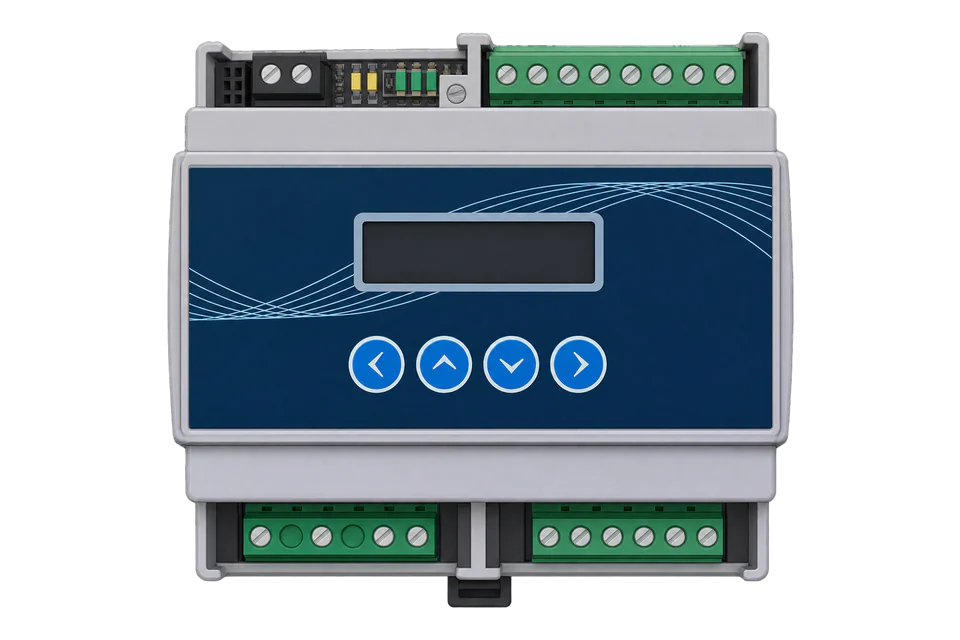
The WattsOn-Mark II (order code W2) is a three-element power and energy meter from Elkor Technologies in London, Ontario. It measures single-phase, split-phase and three-phase circuits up to 347 V L-N and 600 V L-L without PTs, and takes 5 A, 333 mV, milliamp or Rogowski CTs depending on the input version. The M1 version speaks Modbus RTU on RS-485 and the E4 version Modbus TCP on Ethernet or Wi-Fi. Elkor's manual prints every register twice, as a zero-based hexadecimal offset and as a 4xxxx address, and keeps every measurement in both a float block and a scaled integer block. Three debug registers always return fixed values, so the address convention and word order can be proved before any measurement is read.
Compatibility
Compatible with EpiSensor Edge over Modbus RTU or Modbus TCP
The WattsOn-Mark II W2-M1 is compatible with EpiSensor Edge over Modbus RTU on its RS-485 port, read through a ZMB-31 Modbus Interface or a Gateway serial port. The W2-E4 is compatible over Modbus TCP on Ethernet or Wi-Fi. Elkor publishes the full register map with offsets, 4xxxx addresses, data types, units, scale factors and the 32-bit word order in section 6 of the user manual.
WattsOn-Mark II W2-M1 and W2-E4 with any CT input type, using the register tables of user manual Revision 10 (November 2021). Site check: read the Debug 32-bit register at offset 0x511 and expect 1234567, then compare Voltage A with the display or a reference meter. Read-only monitoring: no writes to the configuration, energy reset, lock or system registers.
Connect it with


For a W2-M1 in a panel where a wireless link avoids running a data cable back to the Gateway
- Modbus
- Wireless
- Edge
- Platforms
When the Gateway sits near the meters, or several WattsOn meters share one wired RS-485 line
- Modbus
- Edge
- Platforms
When the WattsOn was ordered as the W2-E4 with Ethernet and Wi-Fi
- Modbus
- Edge
- Platforms
Models
| Models | Interface | Route into Edge |
|---|---|---|
| W2-M1-5A, W2-M1-mA, W2-M1-mV, W2-M1-RC (optional -DL) | RS-485 2-wire with Modbus RTU, 9600 to 230400 baud; two solid-state relay outputs; X.BUS expansion port; optional display and logging module (-DL) | Read the RS-485 port with Modbus RTU through a ZMB-31 or a Gateway serial port. |
| W2-E4-5A, W2-E4-mA, W2-E4-mV, W2-E4-RC (optional -DL) | Ethernet and Wi-Fi (ETport) with Modbus TCP, BACnet/IP, MQTT, web server and HTTP POST; two solid-state relay outputs | Read over Modbus TCP from the Gateway, using the same register map as the M1. The E4's MQTT and HTTP POST outputs push data to other systems and are not an Edge route. |
| W2-M2 (any CT input) | RS-485 2-wire with BACnet MS/TP only, 9600 to 115200 baud | No Modbus port. BACnet MS/TP is not an Edge route, so use the M1 or E4 version where Edge needs to read the meter. |
| W2-E3 and W2-E2 (earlier Ethernet versions) | The manual describes the E3 with Modbus TCP and a web server, and the E2 with BACnet over Ethernet; neither is in the current ordering table | Read an E3 over Modbus TCP with the same map. Edge reads BACnet/IP, so an E2 can be read over BACnet/IP after its objects are confirmed on site. |
Specifications
The WattsOn-Mark II is a three-element, four-quadrant meter that measures and accumulates every quantity per phase, so one unit can meter a three-phase load or up to three separate single-phase circuits with individual CT ratios. It runs from a separate 12 to 30 V DC or 24 V AC supply, mounts on DIN rail or with screws, and is ordered by communication version (M1, M2 or E4), CT input type (5A, mA, mV or RC) and the optional display and logging module (DL).12
- Models
- W2-[1]-[2]-[3]: [1] M1 RS-485 with Modbus RTU, M2 RS-485 with BACnet MS/TP, E4 Ethernet and Wi-Fi; [2] 5A, mA (up to 200 mA), mV (333 mV) or RC (Rogowski coil, up to 360 mV); [3] DL for the display and logging module. Examples: W2-M1-mA and W2-E4-mA-DL.2
- Voltage inputs
- 20 to 347 V AC L-N (600 V AC L-L); 450 V L-N and 780 V L-L absolute maximum; 120/208, 277/480 and 347/600 V delta and wye, single-phase up to 347 V and split-phase; 40 to 70 Hz nominal.2
- Current inputs
- 5A version: 5 A nominal, 10 A maximum. mA version: 200 mA from milliamp-output CTs. mV version: 333 mV, 400 mV maximum. RC and RCH versions: Rogowski coils at 360 mV and 720 mV. 20% continuous overload at full accuracy and 100% momentary current overload. 5 A, mV and mA CTs cannot be mixed on one meter.12
- Accuracy
- ANSI C12.1-2022 Class 0.1, four-quadrant. Current 0.05% typical and 0.1% maximum; voltage, power and energy 0.1% typical and 0.2% maximum; power factor 0.2% maximum; frequency 0.01% maximum. The 2021 manual states ANSI C12.20 Class 0.2.12
- Update rate
- Instantaneous W, VA and VAR every 100 ms (10 Hz); all other parameters every 500 ms (2 Hz). Input bandwidth 2 kHz, to the 33rd harmonic at 60 Hz.2
- Communication
- M1: RS-485 2-wire Modbus RTU, 9600 to 230400 baud, factory 9600 baud, no parity, 8 data bits, 1 stop bit, address from the rotary switch. M2: BACnet MS/TP, 9600 to 115200 baud. E4: Ethernet and Wi-Fi with Modbus TCP, BACnet/IP, MQTT, web server, HTTP POST and SSL.12
- Outputs
- Two solid-state relays, 100 mA at 50 V maximum, programmable for pulse, status or alarm on any measured parameter.2
- Power supply
- 12 to 30 V DC or 24 V AC, less than 2 VA, isolated from the measured lines. The RS-485 common (G) and the supply's - terminal are tied together inside the meter.12
- Housing
- UL 94V-0 plastic enclosure, DIN rail or 3-point screw mounting, 4.2 × 4.3 × 2.4 in; 0.15 kg for mA and mV versions and 0.23 kg for the 5A-DL version.12
- Environment
- Operating -40 to +70 °C, humidity 10 to 90% non-condensing, for a protected installation. Isolation 3500 V AC minimum, input to output.2
- Approvals
- UL listed (file E250395); FCC part 15 Class B emissions.2
Interface
Documented measurements and integration boundaries for WattsOn-Mark II.
- Every row of the map gives an offset in hexadecimal and an address in 4xxxx form: Voltage A is offset 0x220 and address 40545. The offset is the value sent in the Modbus frame, and the address is the offset plus 40001. FC03 and FC04 return the same data, so 30001-based addresses also work for reads.
- 32-bit values occupy two registers with the high-order word at the lower address by default. Register 0x51A (41307) reverses the word order when set to 1, so read it once if a float decodes to a very large or very small number.
- Debug registers return fixed values for checking the convention: Debug 16-bit at 0x510 (41297) reads 12345, Debug 32-bit at 0x511 (41298) reads 1234567 and Debug Floating-Point at 0x513 (41300) reads 1234.567.
- Instantaneous floats, no scaling: Active Power Total 0x200 (40513) in kW, Reactive Power Total 0x202 in kVAR, Apparent Power Total 0x204 in kVA, Voltage Average L-N 0x206, Voltage L-L Average 0x208, Current Average 0x20A, System Power Factor 0x20C and System Frequency 0x20E (40527) in Hz.
- Per-phase floats: Voltage A, B and C at 0x220, 0x222 and 0x224 (40545, 40547, 40549) and AB, BC and AC at 0x226 to 0x22A in volts; Current A, B and C at 0x22C, 0x22E and 0x230 in amps; Active Power A, B and C at 0x232 to 0x236 in kW; reactive power at 0x238 to 0x23C; apparent power at 0x23E to 0x242; power factor at 0x244 to 0x248; Sliding Window Power at 0x256 (40599) in kW.
- The same quantities are repeated as signed 32-bit integers from 0x100 (40257): divide watts, VAR and VA by 10, volts by 100, amps by 1000, power factor by 10000 and frequency by 1000. Voltage A is 0x120 (40289) and Current A 0x12C (40301). Integer power is in W, where the float block is in kW.
- Revenue (non-resettable) energy floats, in kWh, kVAh and kVARh: Net Total Energy 0x1300 (44865), Total Import Energy 0x1304 (44869), Total Export Energy 0x1306 (44871), Q1 to Q4 total reactive energy 0x130C to 0x1312, and per-phase import energy A, B and C at 0x132C, 0x132E and 0x1330. Billing Import and Export Energy at 0x1318 and 0x131A need firmware 11.00 or later.
- Import and export are accumulated per phase: with phases A and B importing 100 W each and C exporting 50 W, Total Import reads 200 Wh and Total Export 50 Wh after an hour. The Billing registers use the direction of the three-phase total instead and would read 150 Wh and 0 Wh.
- Resettable energy floats sit at 0x1100 to 0x115A with the same layout, and integer energy blocks at 0x1000 and 0x1200. Integer energy is divided by the Energy Integer Divider at 0x52E (41327); the register table gives 1000 as its default, so read the divider rather than assume it.
- Identity: Serial Number at 0x51D (32-bit), Hardware, Firmware and Bootloader Version at 0x51F to 0x521 (divide by 100), Model Number at 0x522 (19761 is the M1) and Input Configuration at 0x523 (1 mA, 2 mV, 3 5 A). Device Mode at 0x608 reads 1 when the firmware runs normally and 2 in bootloader mode.
- Configuration and command registers: CT ratios 0x500 to 0x507, PT ratios 0x508 to 0x50F, Energy Reset 0x524, Compatibility Mode 0x525, Passcode and Lock 0x527 to 0x529, Modbus address and serial settings 0x600 to 0x605, and reboot commands 0x609 and 0x60A. Keep all of them out of a monitoring poll.
- Compatibility Mode at 0x525 makes the meter emulate part of the legacy WattsOn-1100 map (floats 0x300 to 0x376). Leave it off unless an existing system was built on the WattsOn-1100 map.
Assessment
WattsOn-Mark II W2-M1 and W2-E4 with any CT input type, using the register tables of user manual Revision 10 (November 2021). Site check: read the Debug 32-bit register at offset 0x511 and expect 1234567, then compare Voltage A with the display or a reference meter. Read-only monitoring: no writes to the configuration, energy reset, lock or system registers.
- InteroperabilityWell supported
- Elkor documents Modbus RTU on the M1 and Modbus TCP on the E4, names the supported function codes, prints every register as both an offset and a 4xxxx address, gives data type, units and scale for each, and provides fixed debug registers to prove the convention. The E4's Modbus TCP port is not stated in the manual.123
- AccuracyWell supported
- ANSI C12.1-2022 Class 0.1, four-quadrant metering with per-phase import, export and net energy, revenue registers that ignore resets, and power updated every 100 ms. Accuracy in service also depends on the CTs and ratios entered.12
- SecurityLimited
- An optional passcode locks every register against writes; the device rejects password attempts for 5 seconds after a wrong one and relocks 10 minutes after an unlock. The meter ships unlocked (Lock register 0x529 reads 0), and Modbus RTU and Modbus TCP have no encryption or authentication. The E4 adds SSL and an administrator password for its web interface. Keep the bus and network private and the client read-only.12
- ReliabilitySupported with conditions
- New serial settings revert unless confirmed within 3 minutes, address 0 restores default serial settings for recovery, Device Mode reports bootloader state, and the MB LED shows solid red when the RS-485 pair is reversed. Elkor does not publish immunity test levels in the retained documents.1
- RuggednessSupported with conditions
- Rated -40 to +70 °C and 10 to 90% RH non-condensing for a protected installation, with 3500 V AC input-to-output isolation and a UL 94V-0 enclosure. The meter has exposed terminals and needs a panel or enclosure.12
Setup
Read the Debug 32-bit register at offset 0x511, then Voltage A at 0x220
Section 6 of user manual Revision 10 lists Debug 32-bit at offset 0x511 (address 41298) as a signed 32-bit register that always reads 1234567, Debug Floating-Point at offset 0x513 (address 41300) reading 1234.567, Voltage A at offset 0x220 (address 40545) as a float in volts and Total Import Energy (Revenue) at offset 0x1304 (address 44869) as a float in kWh. The manual prints both columns, so the address convention is fixed by the document: send the offset.
- Request
- 01 03 05 11 00 02 94 C2: Modbus address 1, FC03, address 0x0511 (the map's offset column for address 41298), two registers, RTU CRC.
- Address convention
- The offset is the zero-based address on the wire and the 4xxxx address is the offset plus 40001: offset 0x0511 is address 41298 and offset 0x0220 is address 40545. A client that numbers holding registers from one takes 1298 and 545 (or 41298 and 40545). Sending 0x0512 for the debug register starts one register late.
- Expected response
- 01 03 04 00 12 D6 87 44 34: four data bytes, high-order word 0x0012 first, then 0xD687.
- Decode
- Signed 32-bit 0x0012D687 = 1234567, the value the manual fixes for this register. A reply of 0xD6870012 means the meter is set to low word first in register 0x51A.
- Float check
- 01 03 05 13 00 02 35 02 reads Debug Floating-Point; the expected response 01 03 04 44 9A 52 25 32 57 gives the float 0x449A5225 = 1234.567.
- Voltage read
- 01 03 02 20 00 02 C4 79 reads two registers from 0x0220. Synthetic response 01 03 04 42 F0 CC CD 7A ED: high-order word 0x42F0 first, then 0xCCCD, so the float is 0x42F0CCCD = 120.4 V.
- Energy read
- 01 03 13 04 00 02 81 4E reads Total Import Energy (Revenue) from 0x1304. Synthetic response 01 03 04 46 6E 1A 66 05 EC gives the float 0x466E1A66 = 15238.6 kWh.
- Acceptance
- Keep the points when both debug registers return their fixed values and Voltage A agrees with the display or a reference meter at the same time. A float read one register late straddles two values and will not decode to the measured voltage.
Acceptance: The debug replies are computed from the fixed values the manual gives, and the voltage and energy replies are a synthetic decoder check, not a captured meter reply. A real reply must return 1234567 and 1234.567 from the debug registers before voltage, current, power and energy points are enabled.
-
Identify the version
Read the order code on the label. A W2-M1 has the Modbus RTU port, a W2-E4 has Ethernet and Wi-Fi with Modbus TCP, and a W2-M2 speaks BACnet MS/TP only. The second field gives the CT input type, which must match the CTs fitted.
-
Set the address and serial settings
Set the rotary switch to the Modbus address: 1 to 9, then A to E for 10 to 14. Position F uses the address stored in register 0x600, and position 0 is for troubleshooting only. From the factory the port runs at 9600 baud, no parity, 8 data bits and 1 stop bit; enter the same values in the Edge serial client or the ZMB-31.
-
Wire the RS-485 port
Connect D+, D- and G on the terminals marked RS-485, not the X.BUS expansion port, and daisy-chain further meters without stubs.
-
Prove the address convention and word order
Send FC03 for two registers at offset 0x511, the Debug 32-bit register. A reply of 1234567 confirms that the offset is sent as written and that the high-order word comes first. Read the Debug Floating-Point register at 0x513 and expect 1234.567.
-
Compare one value with a reference
Read Voltage A at offset 0x220 as a float and compare it with the display or a handheld meter, then check that Current A at 0x22C and Active Power A at 0x232 agree and that power factors read above ±0.700, which Elkor's checklist treats as a sign of correct CT wiring.
-
Add the energy points
Read Total Import Energy (Revenue) at 0x1304 and Total Export Energy (Revenue) at 0x1306 as floats in kWh. Use the revenue block rather than the resettable block, and never write to the Energy Reset, configuration or system registers.
Common questions
- Do I send the offset or the 4xxxx address from the WattsOn map?
- Send the offset. Every row of Elkor's map gives both: Voltage A is offset 0x220, which is address 40545. The offset is the address in the Modbus frame and the 4xxxx address is that offset plus 40001. Elkor's debug register at offset 0x511 always reads 1234567, so one read proves the convention.13
- Which word order does the WattsOn-Mark II use for floats?
- High-order word first by default: the register with the lower address holds the upper 16 bits. Register 0x51A (41307) switches to low word first when set to 1. Read the Debug Floating-Point register at 0x513, which always returns 1234.567, to check the setting.13
- Should I read the float or the integer registers?
- Elkor recommends the floats, which need no scaling: power in kW from 0x200 and energy in kWh from 0x1100 and 0x1300. The integer copies from 0x100 are signed 32-bit values scaled by 10, 100, 1000 or 10000 depending on the quantity, and integer energy is divided by the Energy Integer Divider at 0x52E.1
- What is the difference between the resettable and revenue energy registers?
- The resettable blocks at 0x1000 and 0x1100 clear when 0xA5A5 is written to the Energy Reset register at 0x524. The revenue blocks at 0x1200 and 0x1300 keep their totals through any reset. Elkor advises revenue-grade applications to read the revenue blocks.1
- How do I give a WattsOn an address above 15?
- Turn the rotary switch to F. The meter then uses the address in register 0x600, which defaults to 15 and accepts values up to 247. The change takes effect after a 1 is written to Serial Commit at 0x605 and must be confirmed with a read at the new address within 3 minutes, or the previous settings return. Agree any such write with the site owner.1
- Can one WattsOn meter three single-phase circuits?
- Yes. Every quantity is measured and accumulated per phase, and each channel can take its own CT ratio in registers 0x502, 0x504 and 0x506, provided the CTs are of the same output type. Read Active Power A, B and C at 0x232 to 0x236 and the per-phase import energy at 0x132C to 0x1330.12
Related devices
Sources
- WattsOn-Mark II Precision Energy Meter User Manual, Revision 10 (November 2021), with the Modbus register tables in section 6 and Modbus protocol details in Appendix B (opens in a new tab) (PDF)
- WattsOn-Mark II Precision Energy Meter datasheet, with specifications and ordering information W2-[model]-[CT input]-[DL] (opens in a new tab) (PDF)
- Application Note AN1702, Understanding Modbus Registers, rev A (8 March 2017) (opens in a new tab) (PDF)
- WattsOn-Mark II Installation Quick Reference Guide, with CT ratios and the commissioning checklist (opens in a new tab) (PDF)
Further reading
- ToolModbus register address translator
- ToolModbus data decoder
- ToolModbus CRC and LRC calculator
- GuideModbus register maps: addresses, data types and scaling
- GuideModbus commissioning over RS-485
- GuideContinental Control Systems WattNode Modbus
- ProtocolModbus devices and register maps
- CategoryEnergy meters
Product names and trademarks belong to their owners. Publication does not imply endorsement or a commercial relationship.