Solar PV monitoring
An independent meter on the PV output, another at the grid connection, and the inverter's own registers beside them for context.


- Measure
- PV AC output, site import and export, inverter state, and irradiance where performance has to be normalised
- Calculate
- Solar generation monitoring, grid exchange and site load, with storage and other generators included explicitly
- Sensors
- ZEM-65, Class 0.5S to IEC 62053-22, import and export in both directions Wireless 3-Phase Electricity Monitor datasheet
- On site
- ZGW-20 Gateway, the energy balance, calculated where the meters are Gateway datasheet
Hardware for commercial solar monitoring
For a PV-only site, one meter on generation and one at the grid connection establish the balance. Meter storage and every other on-site generator separately where they exist.
The PV AC output, and the site's grid connection
1 per point three-phase, 3 or 4 wire
- Choose the CT rating for each point: 120 A split-core, or 300 A, 1 kA and 3 kA Rogowski coils
Class 0.5S to IEC 62053-22 with its CTs, 110 to 480 V line to line
Holds both meters and the inverter data, and calculates the balance on site
1 per site up to 250 wireless devices

Inverter registers: DC strings, AC output, state and alarms
1 per inverter bus up to 30 registers
Modbus RTU over RS-485, cable runs to 1,000 m
If performance ratio is being calculated
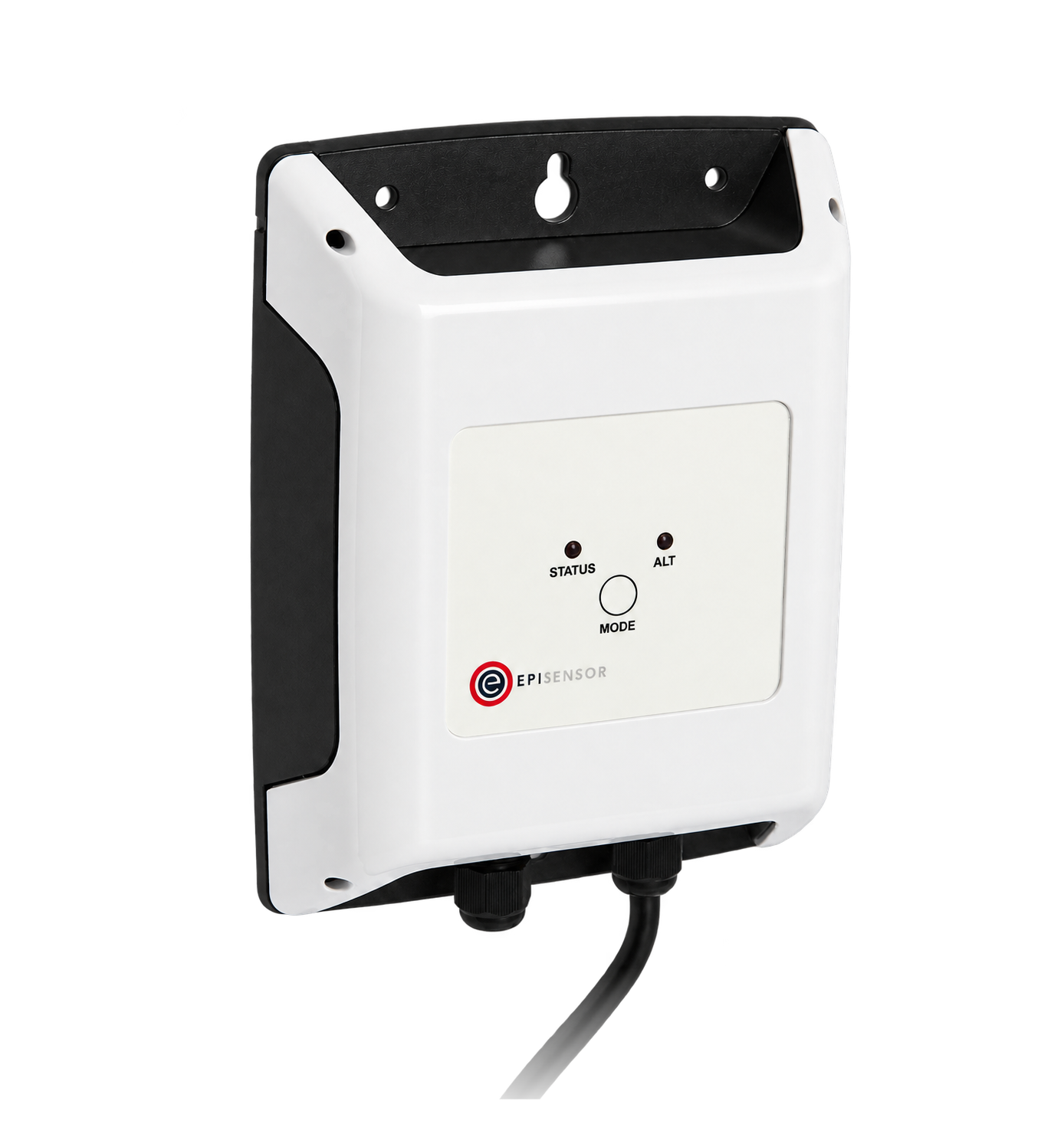
An irradiance or module-temperature transmitter, where performance is normalised
1 per transmitter externally powered loop
The measurements a solar energy balance needs
On a PV-only site, PV generation plus grid import minus grid export equals site load. Storage or another generator adds another term that must be measured with its direction declared.
From field measurement to Edge
Each field signal reaches its named EpiSensor interface, reports through the site Gateway and is handled locally in Edge.
- Wired
- Zigbee
- Edge
- Platforms
| Position | What it tells you | Reference | Sensor |
|---|---|---|---|
| PV AC output | What the plant generated, measured independently of the inverter | State whether the meter covers one inverter, a group or the whole plant Wireless 3-Phase Electricity Monitor datasheet | ZEM-65 (on this page), PV output |
| Grid connection | Import and export, and the sign convention everything else is read against | Confirm CT direction under both import and export | ZEM-65 (on this page), connection |
| Inverter registers | DC strings, operating state and alarms that no AC meter can see | Register availability is model and firmware specific Modbus Interface datasheet | ZMB-31 (on this page) |
| Irradiance | Whether a low day was the plant or the weather | The transmitter's own range, scaling and maintenance plan Analogue Signal Sensor datasheet | ZIO-20 (on this page) |
Expect the inverter and the meter to differ. They measure at different points with different losses between them. A stable difference is normal; a changing one is worth investigating.
Set the sign convention once. Decide that import is positive and export negative, write it down, and check every meter against it during a known export period.
The energy balance in Edge
Site load is derived from the complete energy balance. PV self-consumption can be derived directly only when other generation and storage flows are absent or separately measured.
- Self-consumption is derived
- On a PV-only site, a calculated sensor can take PV generation minus grid export on the same interval. With a battery or another generator, include its separately metered charge, discharge or generation before attributing self-consumption to PV.
- A plant that has stopped
- A limit rule on generation during daylight, or a no-data rule on the inverter, catches a plant that stopped without anybody noticing.
- Both directions are kept
- Import and export stay as separate points rather than one net figure, because a net number hides both.
- Onward wherever it is needed
- Edge exports the balance over MQTT or HTTP to a portfolio system, without the site depending on it.
Commissioning checks
Most solar monitoring arguments are about signs and boundaries. Settle both at commissioning.
-
Each meter is on its stated boundary
Trace both meters on the single-line diagram and write what each one includes.
Pass when the boundaries are on the drawing, and nothing is measured twice.
-
Signs are right in both directions
Watch the connection meter during a known import period and during a known export period.
Pass when import is positive and export negative, on every phase.
-
Meter and inverter are compared
Compare the independent AC meter with the inverter's own total over a full day.
Pass when the difference is stable and explained by the measurement points, not drifting.
-
Night and full output both look right
Check the readings at night, at low generation and at full output.
Pass when night generation is zero rather than a small positive or negative number.
-
Derived numbers are labelled
Look at where self-consumption, performance ratio or avoided carbon appear.
Pass when each one says what it was calculated from, and which system calculated it.
Limits of this measurement
A meter reports energy at a point. The rest is interpretation, and it needs its method stated.
- Inverter data and an independent AC meter can legitimately differ, because they measure at different points.
- Monitoring does not replace inverter protection, grid-code controls or a revenue meter's obligations.
- Performance ratio and avoided-carbon figures need declared methods, reference data and matching periods.
- A string-level fault may not be visible in the AC total at all.
Sources
- IEC 61724 photovoltaic system performance (opens in a new tab) (opens in a new tab) IEC
- Wireless 3-Phase Electricity Monitor datasheet (opens in a new tab) EpiSensor. Specifications, ranges and ordering codes.
Related
-
Battery demand response
A controller that follows grid frequency and sends a set point to the inverter, with independent metering at the connection and the battery. -
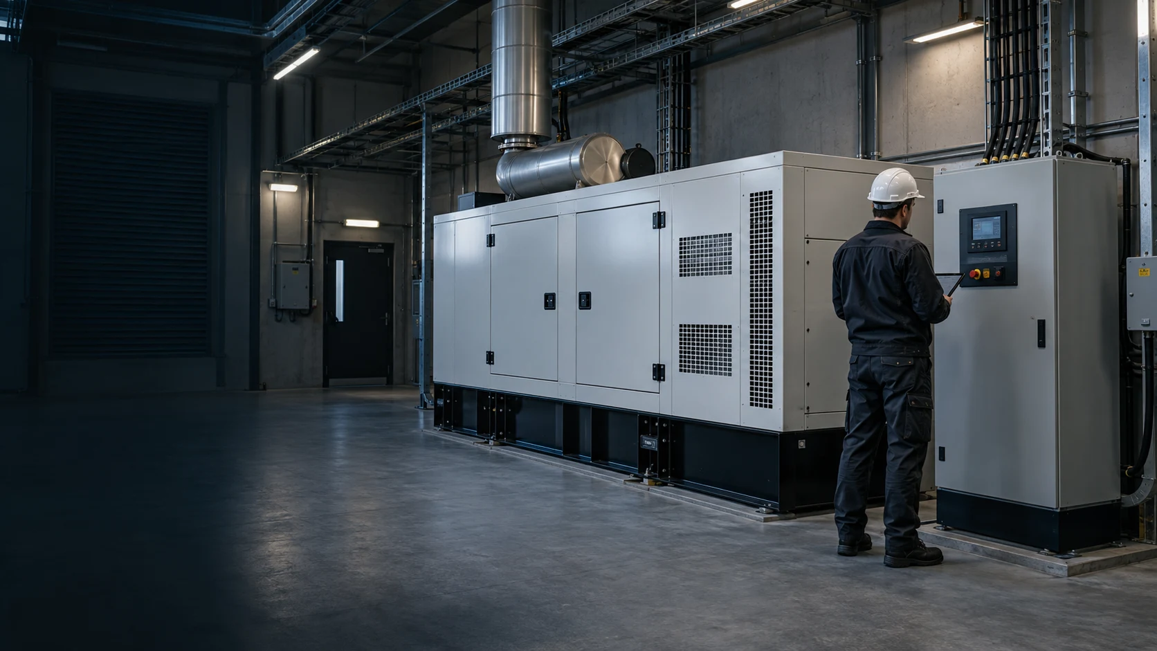
Generator remote monitoring
An independent meter proves what the generator carried, the controller says what it thought it was doing, and the fuel signal says how long it can keep going.
- OverviewEnergy monitoring
- CalculatorThree-phase power calculator
- CalculatorInterval demand calculator
Third-party devices for this application



More in the Device Directory: Energy meters (62), Current transformers (7)
Balance generation, import and export on one site
An engineer can place the meters, check the inverter can be read, and write the balance with you.