Fronius Smart Meter TS
Electricity meter
The Smart Meter TS family measures bidirectional energy flow for a Fronius inverter or Datamanager 2.0. Choose a direct-connected meter or a transformer-connected meter to suit the circuit. The manufacturer documents the RS485/Modbus RTU installation, but the retained TS manuals do not establish a complete direct-meter register and data-validity contract. Direct Edge integration remains unverified.
- Modbus RTU
Electricity meter
Compatibility
Direct Edge integration not yet verified
Fronius documents a meter-to-inverter or Datamanager Modbus RTU link. The retained TS instructions do not define a complete direct-meter function, address, data type, byte and word order, unavailable-value and freshness contract. The Datamanager SunSpec interface is a separate endpoint.
TS 100A-1, TS 65A-3 and TS 5kA-3 only. Smart Meter IP, WR and earlier non-TS models are outside this scope. Obtain exact-model interface evidence and establish ownership of the serial bus before an external read-only client is considered. No writes, resets, export-limit commands or inverter control are included.
Models
| Models | Interface | Route into Edge |
|---|---|---|
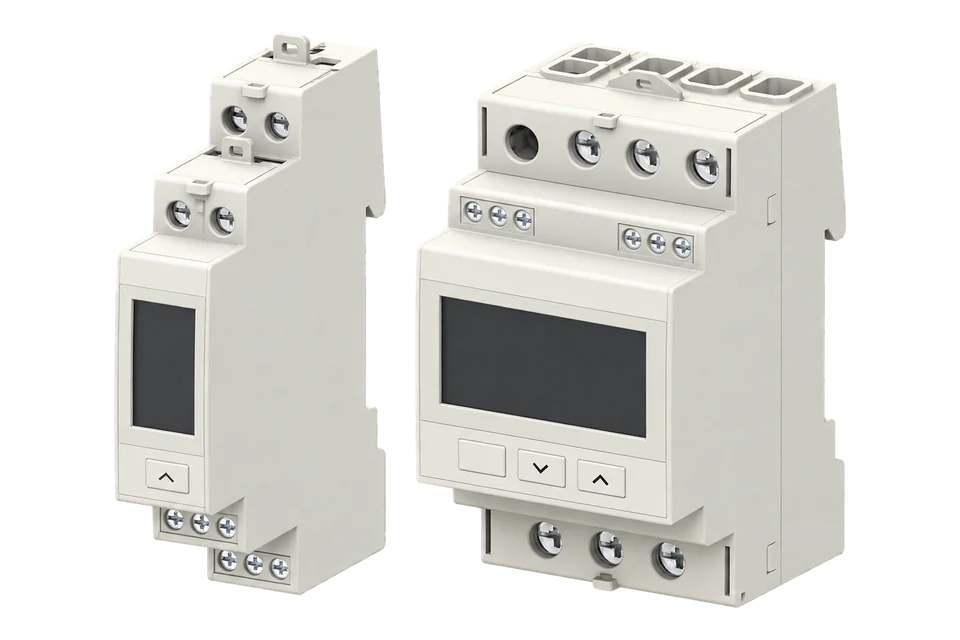
| Fronius Smart Meter TS 100A-1 | Single-phase direct current measurement up to 100 A, nominal 230 V; RS485 with Modbus RTU. | Select for the appropriate single-phase circuit. CAT5 cabling in the instructions carries the serial link; it does not make this an Ethernet meter. |
| Fronius Smart Meter TS 65A-3 | Direct current measurement up to 65 A per phase, nominal 208 to 400 V; RS485 with Modbus RTU. | Match the wiring arrangement and conductor size to the model instructions. Do not apply the transformer-input configuration of the TS 5kA-3. |
| Fronius Smart Meter TS 5kA-3 | Transformer-connected current measurement with nominal 1 A or 5 A secondary inputs and a maximum input of 6 A; RS485 with Modbus RTU. | The 5kA model name is not a direct terminal-current rating. Select the CT ratio, burden, polarity and voltage configuration before commissioning. |
Specifications
Use the exact suffix to select the electrical connection. The two direct-connected models carry circuit current through the meter; the TS 5kA-3 receives current-transformer secondary signals. Transformer ratios and wiring errors affect the complete measurement chain.123
- TS 100A-1 input
- Single phase: nominal 230 V, operating range 161 to 276 V; maximum direct current 100 A.3
- TS 65A-3 input
- Nominal 208 to 400 V, operating range 166.4 to 480 V; maximum direct current 65 A per phase.1
- TS 5kA-3 input
- Nominal 400 to 480 V phase-phase or 230 to 277 V phase-neutral. CT secondary input 1 A or 5 A nominal, 6 A maximum. Current-output CTs are required; voltage-output sensors are excluded.2
- TS 5kA-3 ratios
- kCT and kVT settings each span 1 to 1000. The technical table limits kVT × kCT to 1000 for CT/5A. Check the complete transformer arrangement rather than multiplying the individual maxima.2
- Serial connection
- Electrically isolated, three-conductor RS485 with Modbus RTU. The Fronius setup specifies 9600 baud with no parity; the technical tables specify 8 data bits and 1 stop bit. Broader baud-rate and address ranges differ between menu and technical tables, so confirm the exact installed configuration.123
- Wiring and response
- CAT5 or higher twisted-pair cable; documented inverter-to-meter cable length up to 300 m. Termination uses 120 ohms at the specified bus ends. Listed serial response time is at most 200 ms; this does not specify measurement freshness.123
Interface
Documented measurements and integration boundaries for Smart Meter TS.
- The meters report energy flow to the Fronius inverter or Datamanager. A primary meter represents the configured feed-in or consumption point; secondary meters record individual loads or generators. These installation roles do not define permission for a second Modbus client.
- The direct-connected models distinguish measurement mode A, which totals energy without direction, from mode B, which separates imported and exported energy. Preserve the installed mode and metering location when interpreting a series.
- The retained Datamanager manual describes external SunSpec meter models 201, 202 and 203 for integer values with scale factors, or 211, 212 and 213 for floating-point values. Those models belong to the Datamanager interface and must not be treated as the TS meter’s direct RS485 register map.
- No direct TS function code, register offset, decode order or invalid sentinel is published here. An electrical interface, a working inverter display and a response-time specification do not establish a complete external monitoring contract.
Assessment
TS 100A-1, TS 65A-3 and TS 5kA-3; no released Edge point set or physical-device validation.
- InteroperabilityLimited
- Modbus RTU and the Fronius system connection are documented. The direct TS register and data-validity contract remains incomplete.123
- AccuracySupported with conditions
- Model-specific voltage, current and transformer requirements support selection. Correct circuit configuration, polarity and metering location remain essential.123
- SecurityNot yet assessed
- The retained evidence does not establish authenticated read access or enforced read-only access for a direct external client.123
- ReliabilityNot yet assessed
- The response-time specification does not establish the age or validity of a direct external measurement after startup or communication loss.123
- RuggednessSupported with conditions
- The manuals define DIN-rail mounting and model-specific housing and terminal protection. Select the enclosure and installation conditions for the exact meter.123
Setup
-
Identify the circuit and exact meter
Record the full model, serial number, firmware where available, system wiring and whether the meter is primary or secondary. Select direct or transformer measurement from the circuit requirements.
-
Preserve the Fronius system connection
Record the inverter or Datamanager model, firmware, serial settings, meter address and termination. Do not add another polling master to a bus already operated by the Fronius system without an explicitly supported arrangement.
-
Verify the measurement configuration
For TS 5kA-3, record CT and VT ratios, CT burden, polarity and phase matching. For every model, verify meter location and import/export interpretation against the display and a known circuit condition.
-
Obtain the external read contract
Before an Edge integration, obtain exact endpoint documentation for functions, addresses, lengths, types, scaling, byte and word order, missing values and freshness. Keep Datamanager SunSpec evidence separate from direct TS evidence.
-
Commission a bounded monitoring series
Once that contract is established, compare the selected values and energy changes with independent measurements. Capture startup, disconnection and recovery behavior. Exclude writes and control from the monitoring scope.
Common questions
- Can Datamanager SunSpec registers be used as the TS register map?
- No. The Datamanager manual describes meter data exposed by the Datamanager over Modbus TCP. Its selected SunSpec model, meter identity and sign convention belong to that endpoint. They cannot be copied to the direct TS serial connection.4
- Does TS 5kA-3 carry 5000 A through its terminals?
- No. The meter uses current transformers with nominal 1 A or 5 A secondary outputs; its maximum current input is 6 A. The primary circuit rating depends on the selected transformers and their configured ratios.2
Related devices

Sources
- Fronius Smart Meter TS 65A-3 operating instructions (opens in a new tab)
- Fronius Smart Meter TS 5kA-3 operating instructions (opens in a new tab)
- Fronius Smart Meter TS 100A-1 operating instructions (opens in a new tab)
- Fronius Datamanager Modbus TCP and RTU operating instructions (opens in a new tab)
Further reading
Product names and trademarks belong to their owners. Publication does not imply endorsement or a commercial relationship.