Eastron SDM630MCT V2
CT-connected energy meter
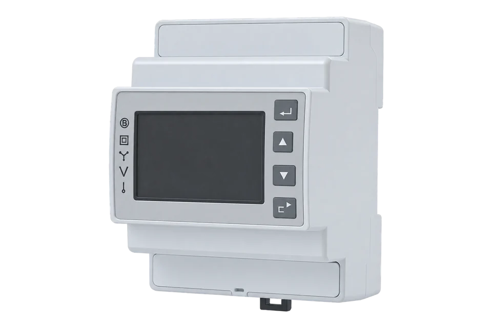
The SDM630MCT V2 measures single-phase and three-phase circuits through external current transformers. Its Modbus measurements reflect the configured CT ratio, making ratio and wiring checks as important as the serial connection.
Compatibility
Compatible through Modbus RTU
Eastron publishes the serial protocol, measurement addresses and float format needed to configure an Edge Modbus client.
SDM630MCT V2 with the RS-485 Modbus RTU interface, covered by Eastron Europe’s V2 series manual and Modbus protocol V1.7. The M-Bus, direct-connected SDM630, Rogowski, TCP and newer-generation models need their own matching documentation. The downloadable starter is narrower: 1 A / 5 A CT input, 3P4W only, with normal word order. Confirm the installed CT settings and compare the returned word order with the meter display before applying it.
Connect it with
-
Modbus Interface ZMB-3XFrom €399 ex VAT Configure Modbus Interface
-
Gateway ZGW-20From €899 ex VAT Configure Gateway


For the Modbus version of SDM630MCT V2
- Modbus
- Edge
- Platforms
Specifications
Choose the MCT version when load current must be measured through external current transformers rather than passing through a direct-connected meter. A 100/5 A CT requires a 5 A secondary setting and ratio 20. The meter then reports primary-side measurements; applying that same ratio again in Edge would multiply readings twice. Wiring topology, phase association and CT polarity must also agree before power and energy are meaningful.1
- Current measurement
- External CTs with 1 A or 5 A secondaries; configure secondary and primary-to-secondary ratio1
- Wiring systems
- Single-phase two-wire, three-phase three-wire or three-phase four-wire1
- Active energy accuracy
- Class 1 to IEC 62053-21 in the V2 manual; external CT error is additional1
- Auxiliary supply
- 85–275 V AC or 120–380 V DC in the cited V2 manual; confirm the installed supply variant1
- Serial settings
- 2400, 4800, 9600, 19200 or 38400 bit/s; none, odd or even parity; one or two stop bits1
- Meter address
- 1–247, unique on the RS-485 segment1
- Other outputs
- Two pulse outputs; pulse settings and RS-485 registers are different collection paths1
Interface
This register map is for the SDM630MCT V2. SDM630MCT V2 Modbus, SDM630MCT V2 dual-tariff / MID versions and SDM630 direct-connected / MCT M-Bus / MCT-RC / MCT-TCP have their own interfaces and are not covered here.
Communication settings
- Interface
- RS-485 Modbus RTU; read the installed baud rate, parity and stop-bit settings
- Unit address
- 1–247; use the installed unique address, not broadcast address 0
- Wiring scope
- 3P4W only for this starter map
- Read with
- FC04 (input registers)
- Word order
- High word first on every value
- Addresses
- Zero-based PDU addresses, as sent on the bus
From SDM630MCT Modbus protocol V1.72 and SDM630 MCT V2 series installation and operating manual1.
Register map
| Point | Address | Hex | Format | Scale | Unit |
|---|---|---|---|---|---|
| Voltage L1-N | 0 | 0x0000 |
FLOAT32 | ×1 | V |
| Voltage L2-N | 2 | 0x0002 |
FLOAT32 | ×1 | V |
| Voltage L3-N | 4 | 0x0004 |
FLOAT32 | ×1 | V |
| Current L1 | 6 | 0x0006 |
FLOAT32 | ×1 | A |
| Current L2 | 8 | 0x0008 |
FLOAT32 | ×1 | A |
| Current L3 | 10 | 0x000A |
FLOAT32 | ×1 | A |
| Active Power L1 | 12 | 0x000C |
FLOAT32 | ×1 | W |
| Active Power L2 | 14 | 0x000E |
FLOAT32 | ×1 | W |
| Active Power L3 | 16 | 0x0010 |
FLOAT32 | ×1 | W |
| Total Active Power | 52 | 0x0034 |
FLOAT32 | ×1 | W |
| Total Apparent Power | 56 | 0x0038 |
FLOAT32 | ×1 | VA |
| Total Reactive Power | 60 | 0x003C |
FLOAT32 | ×1 | VAr |
| Total Power Factor | 62 | 0x003E |
FLOAT32 | ×1 | - |
| Frequency | 70 | 0x0046 |
FLOAT32 | ×1 | Hz |
| Import Active Energy | 72 | 0x0048 |
FLOAT32 | ×1 | kWh |
| Export Active Energy | 74 | 0x004A |
FLOAT32 | ×1 | kWh |
| Import Reactive Energy | 76 | 0x004C |
FLOAT32 | ×1 | kVArh |
| Export Reactive Energy | 78 | 0x004E |
FLOAT32 | ×1 | kVArh |
| Neutral Current | 224 | 0x00E0 |
FLOAT32 | ×1 | A |
Assessment
SDM630MCT V2 with the RS-485 Modbus RTU interface, covered by Eastron Europe’s V2 series manual and Modbus protocol V1.7. The M-Bus, direct-connected SDM630, Rogowski, TCP and newer-generation models need their own matching documentation.
- InteroperabilityWell supported
- A manufacturer protocol defines local FC04 measurements, float32 lengths and configurable register order.2
- AccuracySupported with conditions
- The V2 manual specifies measurement accuracy and CT scaling. Transformer error, wiring and one-time MID settings affect suitability.1
- SecurityNot yet assessed
- Configuration is password-protected, but the cited documents do not establish authenticated or encrypted telemetry.12
- ReliabilitySupported with conditions
- Documented measurement and serial settings support fault diagnosis; valid communication alone does not prove phase or ratio correctness.12
- RuggednessNot yet assessed
- Installation and supply requirements are documented; application-specific environmental qualification needs the exact order variant.1
- ScalabilitySupported with conditions
- Configurable addresses and serial rates permit shared-bus polling, with complete register pairs and one address per meter.2
- LifecycleNot yet assessed
- Public V2 documentation remains available, but that does not establish an end-of-sale or long-term support commitment.1
Edge template
This JSON file supplies the register map. Applying it to an existing meter replaces its sensor list while retaining the site connection, unit ID and enable state.
| Model | Connection | Points | Version | Updated | Download |
|---|---|---|---|---|---|
| SDM630MCT V2 | Modbus | 19 | 1.0.0 | Download |
Downloads need a signed-in account with Edge download access.
Use the template in Edge
- Import the JSON file
In Edge, open Settings, then Devices and Templates. Choose Import JSON and select the downloaded file. Confirm that the model and template name match your device.
- Load the map for your meter
For a new Modbus device, use Load Template before entering the manufacturer or model; it fills those fields and the register list. Set the name, site connection and unit ID, check the polling enable state, then test before saving. For an existing device, apply only to the matching model; this replaces its sensor list but retains its connection, unit ID and enable state.
- Test a reading
Use Test in the wizard and compare a known reading with the meter display. Check its unit, sign and scale, then confirm that timestamps keep advancing. These starter maps are read-only and leave exports off until you configure them.
Setup
Read a complete phase voltage
Protocol V1.7 gives phase 1 line-to-neutral voltage at reference 30001, PDU address 0, as float32 in V for 1P2W and 3P4W. On 3P3W use line 1-to-line 2 voltage at reference 30201, address 200 (0x00C8), with the same FC04/two-register decode.
- Function
- FC04 Read Input Registers
- Request PDU
- 04 00 00 00 02: address 0, quantity 2 registers
- Address 1 RTU frame
- 01 04 00 00 00 02 71 CB, including CRC low byte first
- Independent decoder example
- 43 66 00 00 decodes to 230.0 V with high register first. A reversed register configuration returns the two words in the opposite order.
- Scaling
- Float32 in V; no CT multiplier belongs on this voltage reading.
- 3P3W alternative PDU
- 04 00 C8 00 02: FC04, line 1-to-line 2 voltage at offset 200, two registers in V
Acceptance: The bytes are a synthetic decoder example, not a device capture. Accept the actual read only when the returned word order and value agree with the meter display. The protocol permits reversed register order, so a default assumption is insufficient.
-
Identify the CT-input Modbus version
Record SDM630MCT V2, its communication suffix, firmware and approval markings. Confirm that the installed current transformers have a compatible 1 A or 5 A secondary. A direct-connected SDM630 and a Rogowski-input model are different measurement arrangements.
-
Set topology and CT scaling once
For a 100/5 A CT, choose CT2 = 5 A and CT ratio = 20, not 100. The V2 manual states that the MID-approved version allows the ratio setting only once. Have the installation and ratio checked before committing that setting; do not change it as a communications diagnostic.
-
Match the serial settings
Read the meter’s address, speed, parity and stop bits and set the Edge client to match. Give every meter a unique address. Start with one meter and one measurement, keeping communication errors separate from a genuine zero reading.
-
Verify voltage before interpreting CT readings
For 3P4W or 1P2W, read two input registers at PDU address 0 with FC04 for phase 1 line-to-neutral voltage. For 3P3W use line 1-to-line 2 voltage at address 200 (0x00C8), quantity 2. Decode float32 in V with the installed register order and compare with the display. Voltage does not depend on the CT ratio.
-
Check current, direction and energy
Compare each phase current and total active power with the display under a known load. Verify CT phase association and import/export direction. Do not multiply the returned measurements by the CT ratio again. Check a changing import or export energy counter over a measured interval before using it for totals.
Common questions
- What is the difference between SDM630 and SDM630MCT?
- The direct-connected SDM630 carries the measured current through its terminals. SDM630MCT measures the secondary of external current transformers. CT secondary, ratio and phase wiring are therefore part of MCT commissioning; sharing a Modbus format does not make the hardware interchangeable.1
- For a 100/5 A CT, should I enter 100 or 20?
- The V2 manual calls for CT2 = 5 A and CT ratio = 20, because 100 / 5 = 20. Do not confuse a ratio field with a primary-current field on another meter or generation. Once the meter scales measurements, applying 20 again in Edge would double-scale them.12
- Why does a valid response decode as a tiny number?
- Check float32 decoding and register order. Protocol V1.7 defaults to the most significant register first but supports reversed order. Preserve the order configured on the installed meter and compare voltage with its display; changing meter settings is not necessary just to select the right client decoder.2
- Can the MID ratio be changed later?
- The cited V2 manual warns that the MID-approved version provides only one opportunity to set the ratio. Treat approval and ratio setup as a commissioning decision for the exact variant. Do not use a register write to experiment with CT settings.1
- Can I reuse these specifications on a newer SDM630MCT?
- Use the manual matching the installed generation. This page covers the V2 series and protocol V1.7. Later SDM630MCT and dual-tariff documentation can have different accuracy, configuration and electrical ratings. The model label, approval and firmware are the starting point.12
Related devices


Sources
- SDM630 MCT V2 series installation and operating manual (opens in a new tab) (PDF)
- SDM630MCT Modbus protocol V1.7 (opens in a new tab) (PDF)
Further reading
Product names and trademarks belong to their owners. Publication does not imply endorsement or a commercial relationship.