Eastron SDM120CT-Modbus
Power and energy meter
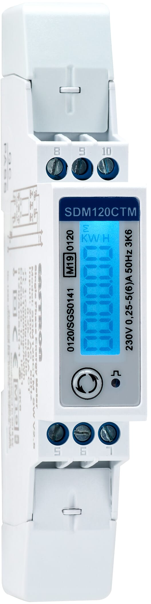
The SDM120CT-Modbus is Eastron's 18 mm single-phase multifunction meter for external current transformers with a 1 A or 5 A secondary. Eastron's own documents and the meter's front panel call the Modbus version SDM120CTM. It measures voltage, current, active, apparent and reactive power, power factor, frequency and demand, and keeps import, export and total counters for active and reactive energy. Every reading is a two-register IEEE 754 float read with FC04, high register first, from voltage at 30001 (PDU address 0x0000) to total active energy at 30343.
Compatibility
Compatible with EpiSensor Edge over Modbus RTU
The SDM120CT-Modbus is compatible with EpiSensor Edge over its RS-485 Modbus RTU port, read through a ZMB-31 Modbus Interface or a Gateway serial port. Eastron publishes the input register map with the reference number, hexadecimal start address, length, float data format and unit of every reading, plus a request and response example that fixes the address convention and the register order.
SDM120CT-Modbus (SDM120CTM) meters with 1 A or 5 A CT inputs, using the SDM120CTM Modbus protocol V1.3 and user manual V1.2. The M-Bus (SDM120CTMB) and pulse-only (SDM120CTP) versions have no Modbus port, and the 40 mA, 100 mA and 100 mV CT versions have their own manuals. Site check: read voltage at 30001 (PDU address 0x0000) and current at 30007 (0x0006) with FC04 and compare both with the display before adding points. Read-only monitoring: no writes to the CT, meter ID, baud rate, pulse, measurement mode or reset registers.
Connect it with
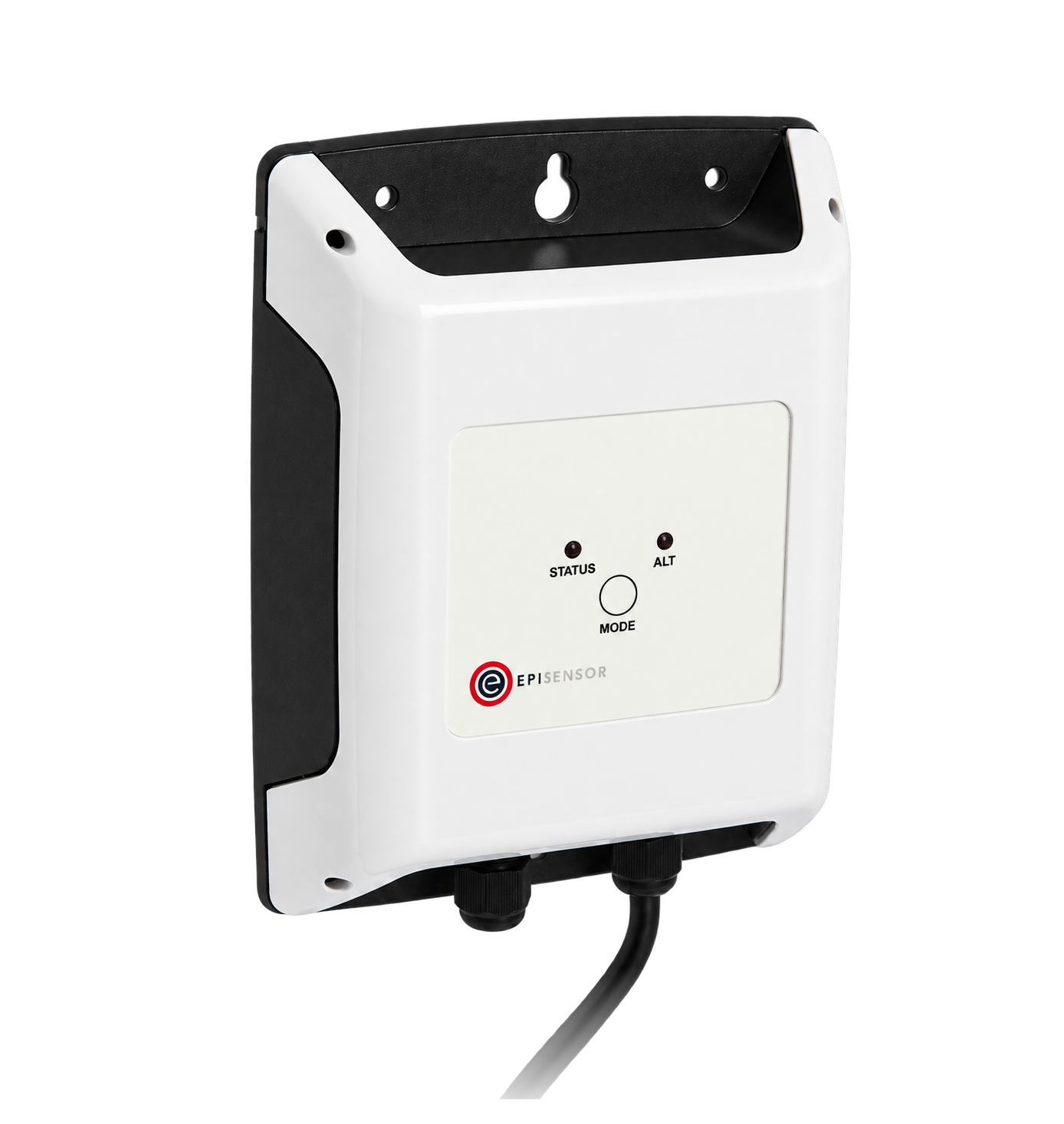
For a meter in a distribution board where a wireless link avoids running a data cable back to the Gateway
- Modbus
- Wireless
- Edge
- Platforms
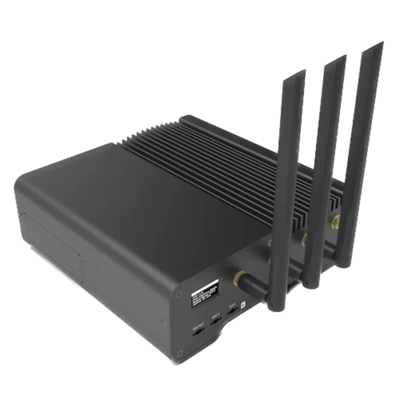
When the Gateway sits near the meter, or several meters share one wired RS-485 bus
- Modbus
- Edge
- Platforms
Models
| Models | Interface | Route into Edge |
|---|---|---|
| SDM120CT-Modbus (SDM120CTM) | RS-485 Modbus RTU on terminals 8 (GND), 9 (B-) and 10 (A+); CT input on terminals 1 and 2 for a 1 A or 5 A secondary; voltage on terminals 3 (N) and 4 (L); two pulse outputs on terminals 5 to 7 | Read the 30001-series float registers with FC04 on the serial path. |
| SDM120CT-Mbus (SDM120CTMB) | M-Bus EN 13757-3 in place of RS-485 Modbus, with the same CT input and pulse outputs | No Modbus port, so this register map does not apply. Check the model on the front label before planning a Modbus read. |
| SDM120CT-Pulse (SDM120CTP) | Two pulse outputs and no serial port | No Modbus port. Count energy from the pulse output instead. |
| SDM120CT 40 mA, 100 mA and 100 mV versions | Modbus versions for low-current or voltage-output CTs, each with its own user manual | Outside this guide. Use the manual and protocol for the exact CT input of the installed meter. |
Specifications
The SDM120CT series is an 18 mm, one-module DIN-rail meter for single-phase two-wire circuits that measures through an external CT. It shows total, import and export kWh, voltage, current, active power, frequency and power factor on a backlit LCD paged with one button, and keeps reactive energy and demand values in its registers. The Modbus version adds an RS-485 Modbus RTU port to the two pulse outputs every version has; Eastron also builds it with M-Bus or with pulse outputs only.23
- Versions
- SDM120CTM (Modbus, sold by Eastron Europe as SDM120CT-Modbus), SDM120CTMB (M-Bus) and SDM120CTP (pulse only), all with two pulse outputs. 40 mA, 100 mA and 100 mV CT-input versions are documented separately.23
- Voltage
- 230 V AC nominal, 176 to 276 V AC in the manual; the datasheet gives 120 V or 230 V AC nominal at 80% to 120% of Un. 50 or 60 Hz. Check the rating on the front label.23
- Current input
- External CT, secondary 1 A or 5 A, base current 5 A. CT primary 5 to 9999 A, set over Modbus or, for the values 5 to 600 A in the manual's list, with the front button.12
- Accuracy
- Active energy class 1 to IEC 62053-21 and class B to EN 50470-1/3; reactive energy class 2 to IEC 62053-23. Voltage 0.5% of range maximum, current 0.5% of nominal, frequency 0.2% of mid-frequency, power factor 1% of unity, active, reactive and apparent power 1% of range maximum.2
- MID
- MID B and D certified to Directive 2014/32/EU, certificate 0120/SGS0141.3
- RS-485
- Modbus RTU, half duplex, on terminals 8 (GND), 9 (B-) and 10 (A+). Meter ID 1 to 247; 1200, 2400, 4800 or 9600 bit/s; parity none, even or odd; 1 or 2 stop bits. Factory settings: ID 1, 2400 bit/s, no parity. Up to 64 meters and 1000 m per bus.123
- Serial setting differences
- The datasheet adds 19200 bit/s and lists one stop bit. The manual and the protocol's baud rate codes stop at 9600 bit/s, and the protocol offers two stop bits only without parity. Read the installed settings on display pages 9 to 11.123
- Pulse outputs
- Two passive outputs. Output 1 is configurable for total, import or export kWh or kVArh at 0.001, 0.01, 0.1 or 1 kWh per pulse, pulse width 200, 100 or 60 ms. Output 2 is fixed at 1000 imp/kWh of total active energy.2
- Consumption and display
- Internal consumption 2 W / 10 VA or less. Backlit LCD, maximum reading 999999 kWh.23
- Housing
- 18 × 118 × 64 mm (W × H × D) to DIN 43880, one module on a 35 mm DIN rail. IP51 for indoor use, self-extinguishing UL94 V-0 material, protective class II.23
- Environment
- Operating -25 to +55 °C, storage -40 to +70 °C, up to 2000 m. The manual gives 0 to 95% RH non-condensing and installation category CAT II; the datasheet gives 90% RH or less in operation and CAT III.23
- Standards
- EMC to EN 61326-1 and EN 61326-2-3, low voltage safety to EN 61010-1, MID Directive 2014/32/EU.3
Interface
Documented measurements and integration boundaries for SDM120CT-Modbus.
- Eastron gives each input register a five-digit reference from 30001 and a hexadecimal start address: voltage is 30001 with start address 00 00, so the PDU address is the reference minus 30001. Send 0x0000 for voltage. A client that numbers registers from one shows the same register as 30001.
- Every reading is a 32-bit IEEE 754 float held in two registers. The protocol's response example sends the high register first and the high byte first, 43 66 33 34 for 230.2 V, and it describes no word-order setting. The start address and the number of registers must both be even: an odd value falls in the middle of a float and the meter returns an error.
- FC04 reads the 3X input registers that carry the measurements. FC03 reads the 4X holding registers that carry the settings. The protocol lists function codes 3, 4, 8 and 16 as valid and says the meter does not answer the broadcast address.
- Instantaneous values: voltage at 30001 (0x00) in V, current at 30007 (0x06) in A, active power at 30013 (0x0C) in W, apparent power at 30019 (0x12) in VA, reactive power at 30025 (0x18) in VAr, power factor at 30031 (0x1E) with no unit, and frequency at 30071 (0x46) in Hz.
- Energy: import active energy at 30073 (0x48) and export active energy at 30075 (0x4A) in kWh, import reactive energy at 30077 (0x4C) and export reactive energy at 30079 (0x4E) in kvarh, total active energy at 30343 (0x156) in kWh and total reactive energy at 30345 (0x158) in kvarh.
- Total active energy follows the measurement mode in holding register 463777 (start address F9 20): mode 1 counts import only, mode 2 counts import plus export and is the default, mode 3 counts import minus export. On a circuit that can export, collect 30073 and 30075 separately rather than relying on the total.
- Demand: total system power demand at 30085 (0x54) and its maximum at 30087 (0x56), import power demand at 30089 (0x58) and its maximum at 30091 (0x5A), export power demand at 30093 (0x5C) and its maximum at 30095 (0x5E), all in W; current demand at 30259 (0x0102) and its maximum at 30265 (0x0108) in A. The demand period is holding register 40003, 60 minutes by default.
- The CT primary is holding register 40051, 5 to 9999 A, and the CT secondary is 40053, 1 A or 5 A; display pages 12 and 13 show both. Compare current at 30007 with the display: when they agree, the register already carries the value the meter shows and Edge needs no extra multiplier.
- The manual gives 999999 kWh as the maximum reading. Up to that value a 32-bit float still resolves 0.0625 kWh or better, so the energy counters keep useful resolution over the meter's range.
- The serial number is holding register 464513 (start address FC 00), an unsigned 32-bit integer in two registers, read only with FC03. It is useful for matching a meter to its record.
- Settings are holding registers: demand period 40003, pulse width 40013, parity and stop bits 40019, meter ID 40021, baud rate 40029, CT primary 40051 and secondary 40053, pulse 1 mode 40087, pulse 1 constant 463761, measurement mode 463777 and the demand reset at 461457. Keep all of them out of a monitoring poll.
- Every page header of the protocol reads "SDM120MVRTU Protocol", while its title and register map name the SDM120CTM; Eastron Europe publishes the file as the SDM120CT Modbus protocol. Confirm the map on the installed meter with the voltage and current reads in the worked check.
Assessment
SDM120CT-Modbus (SDM120CTM) meters with 1 A or 5 A CT inputs, using the SDM120CTM Modbus protocol V1.3 and user manual V1.2. The M-Bus (SDM120CTMB) and pulse-only (SDM120CTP) versions have no Modbus port, and the 40 mA, 100 mA and 100 mV CT versions have their own manuals. Site check: read voltage at 30001 (PDU address 0x0000) and current at 30007 (0x0006) with FC04 and compare both with the display before adding points. Read-only monitoring: no writes to the CT, meter ID, baud rate, pulse, measurement mode or reset registers.
- InteroperabilityWell supported
- Eastron documents Modbus RTU on RS-485 with an input register map giving the reference, hexadecimal start address, length, float format and unit of every reading, and a request and response example with valid CRCs that fixes the address convention and the register order.1
- AccuracySupported with conditions
- Class 1 and MID class B active energy, separate import and export active and reactive energy, power, power factor, frequency and demand. System accuracy also depends on the external CT and the ratio programmed on the meter, and the total counter follows the measurement mode.123
- SecurityNot yet assessed
- The CT, meter ID, baud rate, pulse, measurement mode and demand reset registers are writable over Modbus with FC16, and the manual says the meter parameters can be programmed through the RS-485 port.12
- ReliabilitySupported with conditions
- The protocol documents exception responses and an error for a read that starts or ends inside a float. The datasheet lists electrostatic discharge, fast transient and surge immunity. The datasheet and manual disagree on some serial options, so the installed settings must be read from the display.13
- RuggednessSupported with conditions
- IP51 for indoor use, -25 to +55 °C operating, protective class II. The manual gives installation category CAT II and the datasheet CAT III, so the meter belongs in a closed distribution board.23
Setup
Read voltage from 30001, PDU address 0x0000
The SDM120CTM Modbus protocol V1.3, page 5, lists Voltage at input register 30001, Modbus start address 00 00, length 4 bytes, data format Float, unit Volts, read with function code 04. Its page 3 example reads this register and returns 230.2 V. Use that map as the starting point and compare the result with the display.
- Request
- 01 04 00 00 00 02 71 CB: meter ID 1, FC04, address 0x0000, two registers, RTU CRC. This is the request in Eastron's own example.
- Address convention
- Eastron's reference 30001 has start address 00 00, so send 0x0000. A client that numbers input registers from one shows the same register as 30001. Do not send 30001 or 0x7531 as the address.
- Example response
- 01 04 04 43 66 33 34 1B 38: four data bytes, high register 43 66 first, low register 33 34 second. This is the response printed in the protocol, not a captured reply.
- Decode
- High register first: 0x43663334 as an IEEE 754 32-bit float is 230.2. Read in the other register order the same bytes are 0x33344366, about 4.2 × 10⁻⁸, which shows at once that the client's word order is wrong.
- CT check
- 01 04 00 06 00 02 91 CA reads current at 30007 (0x0006). Its float should agree with the current on display page 5; if it is off by the CT ratio, check the CT primary and secondary on display pages 12 and 13 before adding power and energy points.
- Acceptance
- Keep the points when voltage and current agree with the display at the same time. If they do not, check the meter ID, whether the client has added one to the address, and the register order before adding more points.
Acceptance: Both request CRCs and the protocol's response CRC are independently checked. A real reply must agree with the display before power and energy points are enabled.
-
Identify the meter
Check that the front label reads SDM120CTM and that the meter is the 1 A or 5 A CT version. SDM120CTMB has M-Bus and SDM120CTP has pulse outputs only, and neither carries this register map. Note the CT fitted on the circuit and the CT primary shown on display page 12.
-
Read the serial settings on the meter
Press the button to page through the display: page 9 shows the meter ID, page 10 the baud rate and page 11 the parity. The factory settings are ID 1, 2400 bit/s and no parity. Enter the same values in the Edge serial client or the ZMB-31 and leave the meter's own settings unchanged.
-
Wire the RS-485 pair
Connect A+ to terminal 10 and B- to terminal 9, with terminal 8 as the signal ground where the cable has a reference conductor. Keep the same polarity on every meter, give each meter its own ID from 1 to 247 and terminate the two ends of the line.
-
Make one voltage read
Send FC04 to address 0x0000 for two registers, as in the worked read below, and decode a 32-bit float with the high register first. Compare it with the voltage on display page 4.
-
Check current, then add points
Read current at 0x0006 and compare it with display page 5 to confirm the CT setting. Then add active power, power factor, frequency and the import and export kWh counters at 0x48 and 0x4A, each two registers on an even address, and keep the holding registers out of the polling configuration.
Common questions
- Is SDM120CTM the same meter as SDM120CT-Modbus?
- Yes. Eastron's datasheet lists the Modbus version as SDM120CTModbus and gives SDM120CTM as its meter type, the user manual and protocol are titled SDM120CTM, and the front label reads SDM120CTM. Eastron Europe sells it as SDM120CT-Modbus. The M-Bus version is SDM120CTMB and the pulse version SDM120CTP.123
- Is 30001 the address I send?
- No. 30001 is Eastron's reference number for voltage, and the protocol gives its start address as 00 00, so the PDU address on the wire is 0x0000. Subtract 30001 from any reference in the map. Because every value is two registers on an even address, an address one out falls in the middle of a float and the meter returns an error.1
- What word order does the SDM120CT-Modbus use?
- High register first, high byte first. The protocol's response example returns 43 66 33 34 for 230.2 V, with the high register's high byte first, and the document describes no setting that changes the order. Set Edge to big-endian floats with the high word first and confirm with the voltage read.1
- How is this different from the SDM120-Modbus?
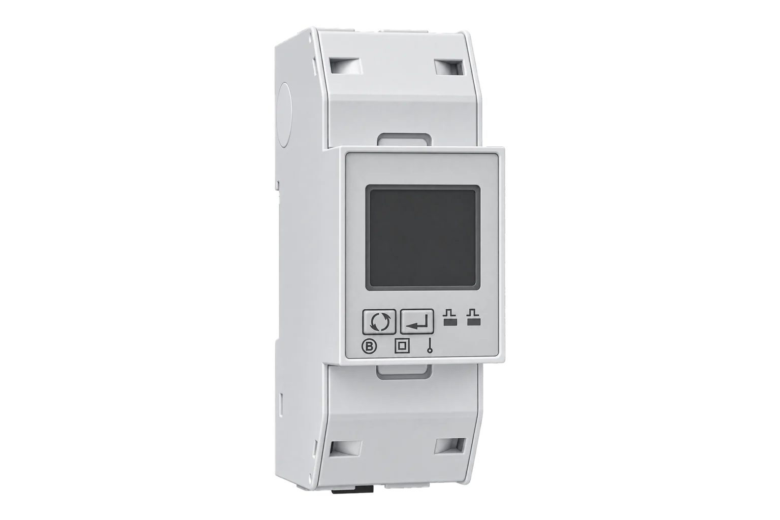
- The SDM120-Modbus carries the load current through its own terminals; its device page covers its ratings and register map. The SDM120CT-Modbus measures through an external CT with a 1 A or 5 A secondary and a primary from 5 to 9999 A, programmed on the meter, so the circuit size is set by the CT rather than by the meter.23
- Does the SDM120CT-Modbus separate import and export energy?
- Yes. Import active energy is at 30073 and export active energy at 30075 in kWh, with import and export reactive energy at 30077 and 30079. Total active energy at 30343 depends on the measurement mode, import plus export by default, so on a circuit with solar generation or other export read the two directional counters separately.1
Related devices
Sources
- Eastron SDM120CTM Smart Meter Modbus Protocol Implementation V1.3, with the FC04 input register map (pages 5 and 6) and the holding register map (pages 7 and 8) (opens in a new tab) (PDF)
- Eastron SDM120CTM user manual V1.2, with specifications, RS-485 settings, display pages and the wiring diagram (opens in a new tab) (PDF)
- Eastron SDM120CT series DIN-rail single-phase datasheet, with the Modbus, M-Bus and pulse versions, MID certificate and bus limits (opens in a new tab) (PDF)
Further reading
- GuideEastron SDM120-Modbus: the direct-connected 45 A version
- GuideEastron SDM630MCT: the three-phase CT-input meter
- ToolModbus register address translator
- ToolModbus data decoder
- ToolModbus CRC and LRC calculator
- GuideCT-connected meters
- ManufacturerEastron devices
- ProtocolModbus devices and register maps
- CategoryEnergy meters
Product names and trademarks belong to their owners. Publication does not imply endorsement or a commercial relationship.