Finder 7M.38 Modbus
Power and energy meter
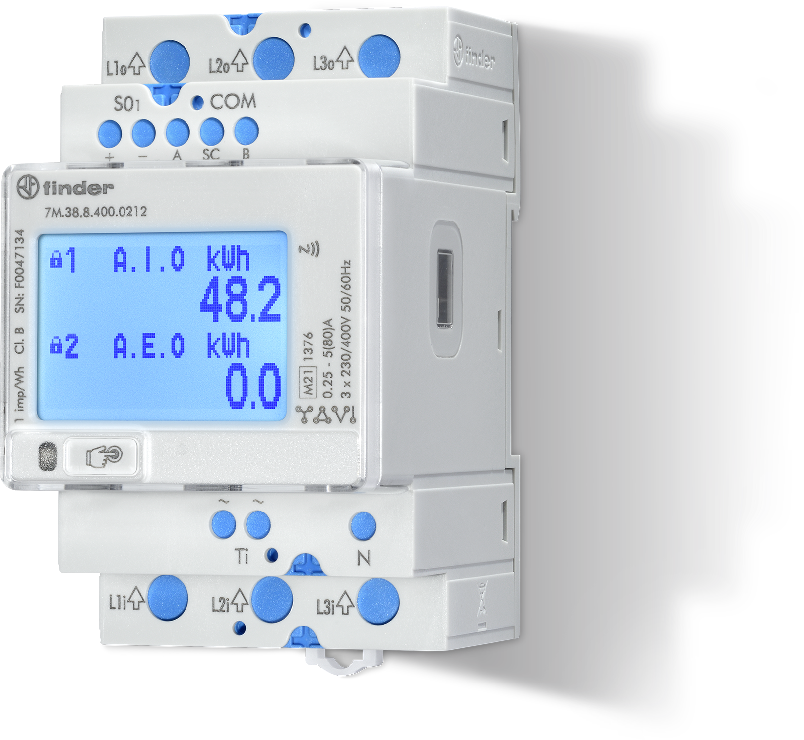
The 7M.38.8.400.0212 is the RS-485 Modbus version of Finder's three-module, three-phase 7M.38 meter for direct connection up to 80 A. It leaves the factory at Modbus address 33, 19200 bit/s, 8 data bits, no parity and 2 stop bits. Finder's register document lists every measurement as an input register read with function code 04, in an IEEE-754 Float32 block in V, A, W and Wh, and again in Finder's own packed integer formats.
Compatibility
Compatible with EpiSensor Edge over Modbus RTU
Finder documents Modbus RTU over RS-485 for the 7M.38.8.400.0212 and publishes its input register map with function codes, data types, units and an example request frame that fixes the address convention. This is documented compatibility, without a physical Edge test.
Finder 7M.38.8.400.0212 on its RS-485 terminals, using the 7M38 tables in Modbus communication protocol 7M24 - 7M38, edition 07/2026, as a best-effort starting point. Compare the first read with the meter display. The 7M.38.8.400.0112 (no RS-485 port), the 7M.38.8.400.0312 (M-Bus), the side infrared port and the 7M.24 single-phase tables are outside this guide. Read-only monitoring.
Connect it with
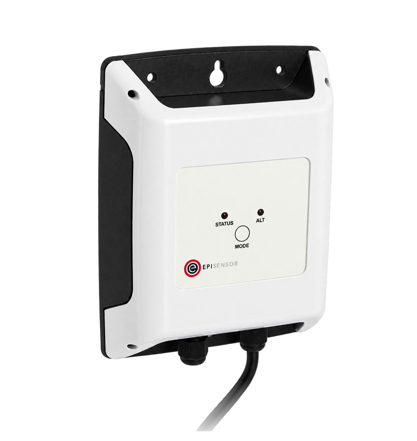
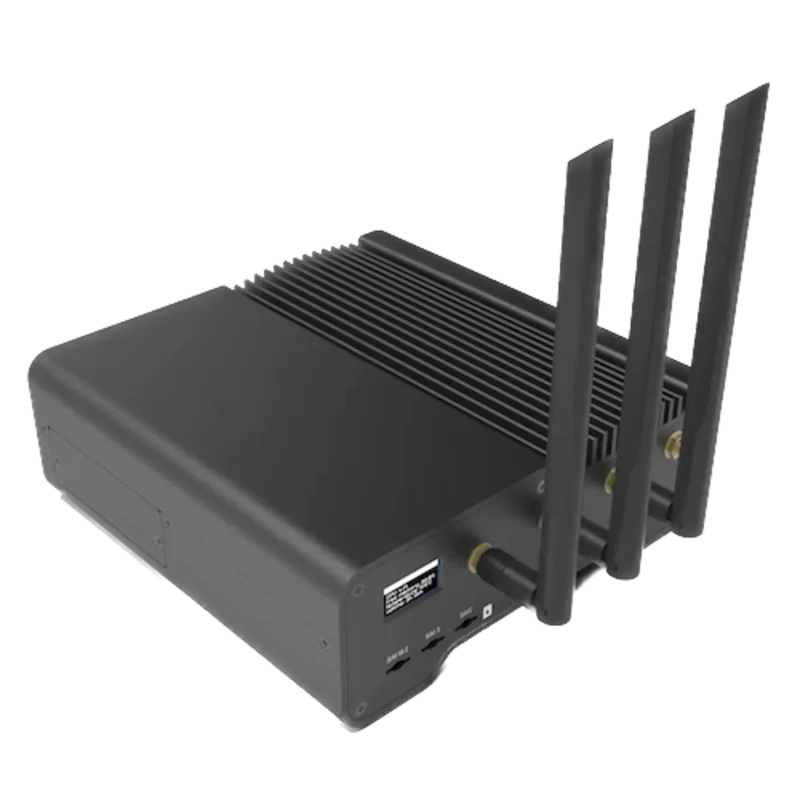
For the 7M.38.8.400.0212 RS-485 port on the COM terminals A, SC and B
- Modbus
- Edge
- Platforms
Models
| Models | Interface | Route into Edge |
|---|---|---|
| 7M.38.8.400.0212 | RS-485 Modbus RTU on COM terminals A, SC (shield) and B; one S0 output; infrared port; NFC; 230 V tariff input | Read the 7M38 input registers with FC04 on the serial path. |
| 7M.38.8.400.0112 | Two S0 pulse outputs, infrared port and NFC; no RS-485 port | No RS-485 Modbus port, so the register map in this guide does not apply. |
| 7M.38.8.400.0312 | M-Bus on COM terminals M+ and M-, one S0 output, infrared port and NFC | M-Bus, not Modbus, so the register map in this guide does not apply. |
Specifications
Finder makes three 7M.38 three-phase meters on the same hardware. Only the 7M.38.8.400.0212 has the RS-485 Modbus port. All three measure directly up to 80 A, count imported and exported energy, carry MID approval for their non-resettable active energy counters, and switch two tariffs from a 230 V input.235
- Exact version
- 7M.38.8.400.0212: RS485 Modbus integrated interface, S0 pulse output, IR port and NFC, dual tariff, conforms to MID.24
- Voltage
- 3 x 230/400 V AC, operating range 0.8 to 1.15 Un, 50/60 Hz. Connection 3L+N, 3L, single-phase L+N on L3, or 3L-2I (Aron), chosen once at installation.24
- Current
- Direct connection. Reference 5 A, maximum 80 A, minimum measured 0.25 A, starting 0.02 A, accuracy range 0.5 to 80 A.2
- Accuracy and approval
- Active energy class B to EN 50470-3 (MID) and class 1 to EN 62053-21; reactive energy class 2 to EN 62053-23. MID approval applies to the non-resettable active energy counters.23
- RS-485
- Modbus RTU on COM terminals A, SC (shield) and B, galvanically isolated from the mains circuit. Factory address 33 (1 to 247). Default 19200 bit/s, 8 data bits, no parity, 2 stop bits; 1200 to 115200 bit/s, parity none, odd or even, 1 or 2 stop bits.234
- Bus
- Up to 32 Modbus meters and 1000 m of bus.2
- Other interfaces
- S0 output, 500 imp/kWh, 32 ms, 3.3 to 27 V DC and 27 mA; front LED 1000 imp/kWh; 230 V tariff input; side infrared port (Modbus RTU at 19200 bit/s 8N2, address 33, fixed) for setup with a USB adapter; NFC for Finder's Toolbox NFC app.23
Interface
Documented measurements and integration boundaries for 7M.38 Modbus.
- Read measurements with FC04. Finder sends the listed register minus 30000: 32500 goes on the wire as 2500 (0x09C4). Settings are holding registers read with FC03, listed register minus 40000.
- L1, L2 and L3 voltage at 32500, 32502 and 32504; line voltages U12, U23 and U31 at 32508, 32510 and 32512: two registers, Float32, V.
- L1, L2 and L3 current at 32516, 32518 and 32520, and current sum at 32522: Float32, A.
- Active power L1 to L3 at 32530, 32532 and 32534 and total at 32536 (W); reactive power at 32538 to 32544 (var); apparent power at 32546 to 32552 (VA): Float32, total last in each group.
- Power factor L1 to L3 at 32554, 32556 and 32558 and total at 32560; frequency at 32584 (Hz): Float32.
- Non-resettable energy counters n1 to n4 at 32752, 32754, 32756 and 32758: Float32 in Wh or varh. The same counters as 32-bit signed integers (T3) are at 30406, 30408, 30410 and 30412, scaled by 10 to the power of the signed exponent in 30401 to 30404.
- Resettable counters 1 to 16 at 32760 to 32790 (Float32), or as T3 at 30414 to 30444 with exponents at 30446 to 30461. Higher-resolution copies of all twenty counters (T3, x 0.1 Wh or varh) are at 30462 to 30501.
- The same instantaneous values in Finder's packed formats: frequency 30105 and U1 30107 (T5), I1 30126 (T5), total active power 30140 (T6, W), total power factor 30164 (T7). T5 and T6 carry a signed decade exponent in the top byte.
- Identity: model number at 30001 (eight registers, text), serial number at 30009 (four registers, text), software version at 30013, maximum registers per read at 30099 and device group at 39000 (5 means 7M).
- Which quantity each counter n1 to n4 holds is configured in the holding registers 40421, 40425, 40429 and 40433 (read with FC03). Phase validity flags are at 30101 and the checksum status at 30400.
Assessment
Finder 7M.38.8.400.0212 on its RS-485 terminals, using the 7M38 tables in Modbus communication protocol 7M24 - 7M38, edition 07/2026, as a best-effort starting point. Compare the first read with the meter display. The 7M.38.8.400.0112 (no RS-485 port), the 7M.38.8.400.0312 (M-Bus), the side infrared port and the 7M.24 single-phase tables are outside this guide. Read-only monitoring.
- InteroperabilityWell supported
- Finder names Modbus RTU on RS-485 for the 0212 and publishes function codes, register lengths, data types, units and a worked request frame that fixes the address convention. Default serial settings are in the manual, leaflet and datasheet.123
- AccuracySupported with conditions
- Class B (MID) active and class 2 reactive energy with per-phase voltage, current, power, power factor and THD, and separate import and export counting. Counter assignment is configurable, the connection mode is fixed at installation, and the 3L-2I connection gives line-to-line values only.123
- SecurityLimited
- Settings are grouped by protection level, with two four-letter user passwords and a MID lock. Over Modbus, a password is written with FC16 in clear text, and RS-485 Modbus RTU has no encryption or peer authentication. Keep the bus inside the panel and send reads only.13
- ReliabilitySupported with conditions
- Powered from the measured supply over 0.8 to 1.15 Un. Finder publishes EMC levels (8 kV contact discharge, 4 kV burst and surge on the supply, 2 kV burst on the bus terminals), 4 kV AC isolation between supply and Modbus, and a checksum status register. NFC reads the counters without mains. Treat failed reads as missing data.123
- RuggednessSupported with conditions
- Rated -25 to +70 °C with IP50 housing and IP20 terminals, as an indoor meter (M1, E2) with vibration and shock testing to EN 60068-2-6 and 2-27. Install it in an enclosure.23
Setup
Read L1 voltage from register 32500
Finder's Modbus communication protocol 7M24 - 7M38, edition 07/2026, lists U1 in the 7M38 Float32 block at registers 32500 and 32501, function code 4, data type T_float, unit V. Use that map as the starting point and compare the result with the display.
- Request
- 21 04 09 C4 00 02 34 CA: address 33 (0x21, the factory default), FC04, address 0x09C4, two registers, RTU CRC.
- Address convention
- Finder subtracts 30000 from the listed register: its own example sends 00 6B (107) for register 30107. Register 32500 is therefore 2500 (0x09C4) on the wire. A client that numbers input registers from one, with 30001 as the first, shows it as 32501. Do not send 32500 or 2499.
- Synthetic response
- 21 04 04 43 66 00 00 2F DD: four data bytes, 43 66 00 00.
- Decode
- High word first, high byte first, as in Finder's frame example: 0x43660000 as an IEEE-754 Float32 is 230.0 V. No scaling factor applies.
- Cross-check
- The same voltage in Finder's T5 format is at register 30107 (0x006B): 21 04 00 6B 00 02 07 77. A reply of FE 00 59 D8 is exponent -2 and value 23000, so 230.00 V.
- Acceptance
- Keep the point when it agrees with L1 voltage on the meter display at the same time. If it does not, check the address, the serial settings and the word order before adding more points.
Acceptance: The response bytes are a synthetic decoder check, not a captured meter reply. A real reply must agree with the display before current, power and energy points are enabled.
-
Identify the meter version
Read 7M.38.8.400.0212 on the front label; the 0112 and 0312 versions have no RS-485 Modbus port. Record the serial number and the firmware details shown in the Info menu.
-
Read the serial settings without changing them
Settings, then Communication, shows the device address, bits per second, parity and stop bits. A meter that has not been configured answers at address 33, 19200 bit/s, 8 data bits, no parity and 2 stop bits. Enter the same values in the Edge serial client.
-
Wire the RS-485 pair
Connect the bus to COM terminals A and B and the cable shield to SC. Every new meter ships at address 33, so give each one its own address before it joins a shared bus. Finder allows up to 32 meters on 1000 m of bus.
-
Make one voltage read
Send FC04 to address 2500 (register 32500) for two registers and decode the Float32 high word first, as in the worked read below. Compare the result with L1 voltage on the display.
-
Check which energy each counter holds
Counters n1 to n4 can be assigned to different energy types. Read 40421, 40425, 40429 and 40433 with FC03 and compare them with the lock-marked counters 1 to 4 and their codes (A.I.0, A.E.0 and so on) on the display before naming the energy points.
-
Add the points you need
Add current, power and energy registers from the same tables. Read the per-read limit at 30099 before grouping registers, and keep FC06 and FC16 writes out of the polling configuration.
Common questions
- Do I send 32500 as the register address?
- No. The document sets the input register base at 30000 and its example request sends 00 6B, decimal 107, for register 30107. Send 2500 for register 32500. A tool that asks for one-based 3xxxx register numbers needs 32501.1
- Which energy counter is import and which is export?
- It depends on configuration. The four non-resettable counters can each be set to active, reactive or apparent energy, with the counted quadrants chosen separately, and the map's unit column gives n1 to n4 as Wh, varh, Wh and varh. The display marks them 1 to 4 with a lock and a code such as A.I.0 (active import) or A.E.0 (active export). Match those codes to 40421, 40425, 40429 and 40433 before you name the points.13
- Why does Finder's own example decode to a different voltage?
- The example reply FE 00 59 74 decodes by the T5 rule to exponent -2 and value 22900, which is 229.00 V; the document prints 229.34 V. Decode with the data type table and confirm against the display.1
- Where are the high-resolution energy counters?
- The introduction to the document says registers 30426 to 30441. In the 7M38 table those addresses are resettable counters 7 to 14; the higher-resolution copies, in steps of 0.1 Wh or varh, are at 30462 to 30501. Use the table.1
- Does the map include writable registers?
- Yes. FC06 and FC16 change the address, speed, parity, tariff, counter configuration and passwords, and FC06 to 40031 resets the resettable counters. The connection mode is set once and cannot be changed afterwards. A monitoring configuration should read with FC04 and FC03 only.13
- Does a Float32 energy counter lose resolution?
- Yes. The Float32 counters are in Wh, and a Float32 holds integers exactly only up to 16,777,216: above about 16,777 kWh the value moves in steps of 2 Wh, above 134,218 kWh in steps of 16 Wh and above 1,073,742 kWh in steps of 128 Wh. For long-term totals read the T3 counter with its exponent, and calculate consumption over intervals.1
Related devices
Sources
- Modbus communication protocol 7M24 - 7M38, edition 07/2026 (opens in a new tab) (PDF)
- 7M series energy meters datasheet, edition VI-2026 (opens in a new tab) (PDF)
- User's manual 7M.38 three-phase meters 7M.38.8.400.0112, 0212 and 0312, edition 06/2026 (opens in a new tab) (PDF)
- 7M.38 instruction leaflet IB7M38, edition 06/26 (opens in a new tab) (PDF)
- Type 7M.38 three-phase multi-function bi-directional energy meters product page (opens in a new tab)
Further reading
Product names and trademarks belong to their owners. Publication does not imply endorsement or a commercial relationship.