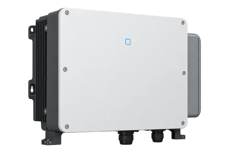
Sungrow SG150CX
Commercial PV inverter
Sungrow identifies the SG150CX as type 0x2C57 in its inverter protocol. Its RS485_1 terminal is a monitoring path, while RS485_3 belongs to the external energy meter. A read-only RTU connection can check identity and active power when the installed communication module and serial-bus owner permit it. COM1 WiNet-S2 Ethernet is a separate optional module, not the direct RS-485 terminal.
- Modbus RTU
Commercial PV inverter
Compatibility
Compatible through a qualified Modbus RTU monitoring path
The SG150CX manual Ver17 names RS485_1 as a monitoring connection, and Sungrow protocol V1.1.80 explicitly identifies SG150CX as type 0x2C57 with FC04 running-information registers.
SG150CX international model, manual Ver17 (June 2026) and protocol V1.1.80 (March 2026). Check the installed market suffix and software against these documents. The SG150CX-CN types are distinct; an existing WiNet-S2 or logger may rule out a second RS-485 client. No site-tested configuration is asserted.
Connect it with
-
Modbus Interface ZMB-3XFrom €399 ex VAT Configure Modbus Interface
-
Gateway ZGW-20From €899 ex VAT Configure Gateway


The system owner approves an exclusive RTU master and the installed WiNet-S2 or logger does not conflict
- Modbus
- Edge
- Platforms
Models
| Models | Interface | Route into Edge |
|---|---|---|
| SG150CX | Seven MPPTs, three strings each; RS485_1 A1/B1 monitoring; protocol type 0x2C57 | Read-only FC04 through one approved RS-485 master. |
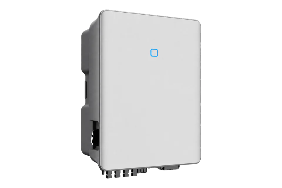
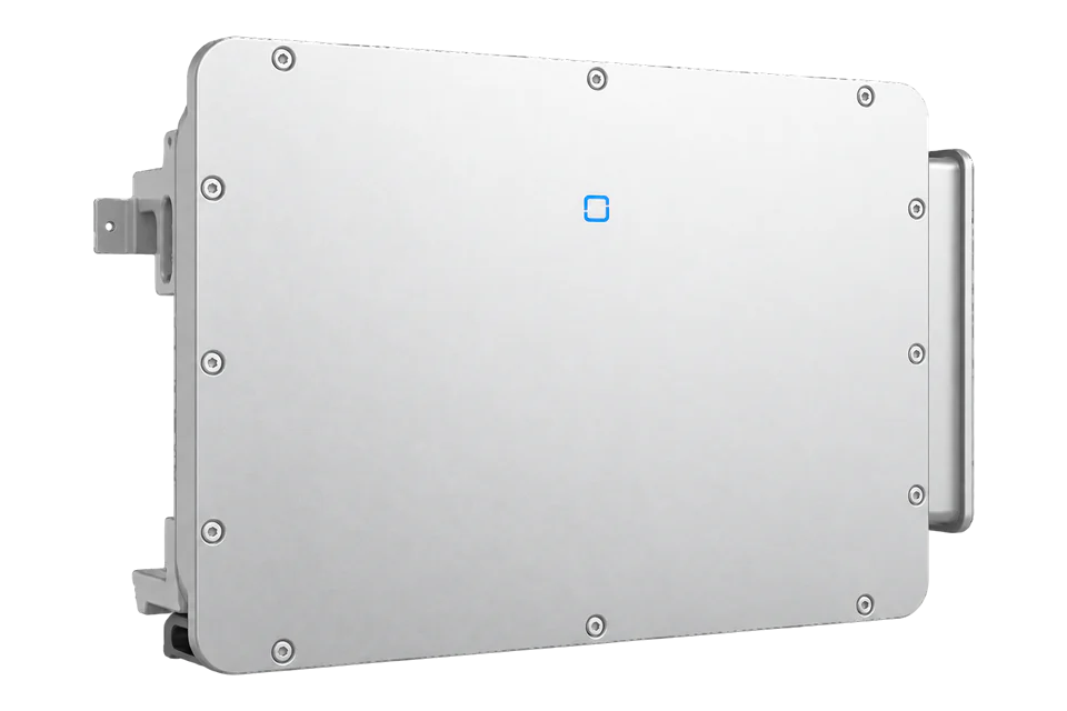
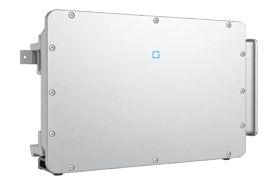
| SG150CX-CN-V11, SG150CX-CN-V12, SG125CX-P2 | Separate protocol type codes, markets or enclosures | Check the exact nameplate and returned type code; do not reuse this guide for another suffix. |
Specifications
The SG150CX manual Ver17 assigns RS485_1 A1/B1 to an external monitoring box or other monitoring device, RS485_2 to an external box or cascade and RS485_3 A3/B3 to the external energy meter. COM1 can host an optional WiNet-S2 Ethernet/WLAN module. The manual prohibits simultaneous use of that communication module and a third-party RS-485 data logger.1
- AC rating
- 150 kW rated output; check the installed 380/400/415/480 V regional variant1
- Monitoring terminals
- RS485_1 A1/B1 differential pair; not the COM1 WiNet-S2 Ethernet connection1
- Meter terminals
- RS485_3 A3/B3 is assigned to the external meter1
- RTU defaults
- 9600 bit/s, eight data bits, one stop bit, no parity by default; slave address 1 by default, settable 1–2472
- Identity read
- FC04 at one-based register 5000, wire address 4999, returns 0x2C57 for SG150CX2
- Active-power read
- FC04 at registers 5031–5032, wire start 5030; signed 32-bit watts, low word first2
Interface
Documented measurements and integration boundaries for SG150CX.
- Device type 0x2C57 establishes that a register response belongs to the SG150CX, not a CN suffix or another Sungrow model.
- The read-only running-information map covers active power, yield, work state and selected MPPT values; the model has seven MPPTs.
- A plant or grid connection meter, measured independently, is needed to establish export and flexibility delivery. Inverter telemetry is not settlement evidence.
Assessment
SG150CX with the documented RS485_1 interface and protocol V1.1.80. A design and bounded read, not a site test or approved control.
- InteroperabilitySupported with conditions
- The exact SG150CX manual identifies RS485_1 for monitoring and the protocol specifies this model type; logger ownership limits the connection.12
- AccuracySupported with conditions
- Signed watts, word order and address convention are documented. Separate boundary metering remains necessary for export.2
- SecurityNot yet assessed
- The cited RTU link does not establish authenticated or encrypted device messages; control physical access to the serial bus.12
- ReliabilityNot yet assessed
- No installed-site uptime or backfill guarantee is established for a third-party RS-485 client.1
- RuggednessSupported with conditions
- The manual specifies the outdoor enclosure and operating limits, subject to the installed regional variant.1
Setup
Identify SG150CX before decoding output
These are synthetic read examples, not readings from a commissioned plant. Use the actual unit ID and check a complete response frame including CRC.
- Identity request
- FC04, wire address 4999 (0x1387), quantity 1; accept device type 0x2C57.
- Power request
- FC04, wire address 5030 (0x13A6), quantity 2 for registers 5031–5032.
- Synthetic power data
- 0x49F0 followed by 0x0002 combines low word first to 0x000249F0, or 150000 W.
- Unavailable value
- 0x7FFFFFFF is the signed 32-bit unavailable sentinel; do not plot it as output.
- Acceptance boundary
- Verify type, function, byte count, CRC, sign, word order and units against a local reference.
Acceptance: A verified FC04 read is a monitoring path. It does not prove command authority or delivered grid response.
-
Record the complete nameplate including any market suffix, installed firmware, existing WiNet-S2 or communication box, the meter wiring and the owner of the RS-485 bus.
The SG150CX-CN variants have different type codes.
-
Agree an exclusive RTU-master design before connecting to RS485_1 A1/B1.
Keep RS485_3 meter wiring, local stop, alarms and grid protection untouched. Do not attach a parallel third-party logger beside the communication module.
-
Confirm slave address and serial framing on the commissioned system.
The protocol defaults of 9600 bit/s, 8N1 and slave 1 are starting points, not proof of the installed setting.
-
Use FC04 at wire address 4999 to read one register.
Require 0x2C57 and a complete CRC-checked response before applying the SG150CX map.
-
Read FC04 at wire start 5030, quantity two.
Decode low word first as signed 32-bit watts; reject the unavailable sentinel and compare with a contemporaneous local reference.
-
Exclude all active-power limits, grid-code, stop and reactive-power writes from this monitoring guide.
Check a separate connection-point measurement before any flexibility claim.
Related devices
Sources
- SG150CX PV grid-connected inverter user manual, Ver17, June 2026 (opens in a new tab) (PDF)
- Communication Protocol of Residential & Commercial PV Grid-Connected Inverters V1.1.80 (opens in a new tab) (PDF)
Further reading
- ApplicationSolar inverter monitoring across a PV fleet
- ApplicationZero-export solar curtailment monitoring
- ToolModbus data decoder
- ToolPV string sizing
- ToolModbus register address converter
- ToolRS-485 termination and bias
- GuideModbus RS-485 commissioning
- ManufacturerSungrow devices
- ProtocolModbus devices and register maps
- CategoryInverters and charge controllers
Product names and trademarks belong to their owners. Publication does not imply endorsement or a commercial relationship.