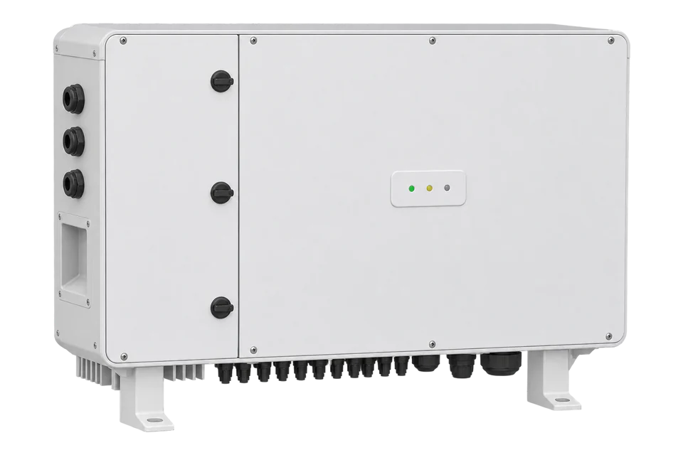
FIMER PVS-50/60-TL
Commercial PV inverter
FIMER PVS-50-TL and PVS-60-TL inverters connect to EpiSensor Edge over Modbus RTU on the RS485-2 or RS485-MAIN line, or over Modbus TCP on Ethernet. FIMER's SunSpec PICS Rev 3 gives the address of every model: Common at 40002, three-phase inverter model 103 at 40070 and multiple MPPT model 160 at 41104. Read the model headers first, then AC power with its scale factor.
Compatibility
Compatible with EpiSensor Edge over Modbus RTU or Modbus TCP
The PVS-50/60-TL product manual Rev F documents Modbus RTU (SunSpec protocol) on RS485-2 and RS485-MAIN and a Modbus server setting for TCP/IP. FIMER's SunSpec PICS Rev 3 gives the implemented models, addresses, data types and scale factors. Edge reads them as a Modbus RTU client through a ZMB-31 Modbus Interface or the Gateway serial port, or as a Modbus TCP client.
PVS-50-TL and PVS-60-TL in the standard, -SX and -SX2 versions, with inverter firmware 1827B or later as stated in SunSpec PICS Rev 3, and product manual Rev F. PVS-60-TL-US has its own product manual and is outside this guide. Site check: read the Common and model 103 headers, then compare AC power with the inverter display.
Connect it with


When RS485-2 is free and its protocol can be set to Modbus Sunspec Server
- Modbus
- Wireless
- Edge
- Platforms
When RS485-MAIN is in its default slave setting and no meter or weather station needs it in master mode
- Modbus
- Wireless
- Edge
- Platforms
When the inverter's Ethernet daisy chain is on the site network
- Modbus
- Edge
- Platforms
Models
| Models | Interface | Route into Edge |
|---|---|---|
| PVS-50-TL, PVS-50-TL-SX, PVS-50-TL-SX2 | 50 kW at 400 Vac; Md string -3P74- in the Common model | Read model 103 for AC values and model 160 for MPPT voltages; the SX and SX2 versions have three MPPTs. |
| PVS-60-TL, PVS-60-TL-SX, PVS-60-TL-SX2 | 60 kW at 480 Vac; Md string -3P75- in the Common model | Same SunSpec addresses as the PVS-50-TL; confirm Md before naming points. |
| PVS-60-TL-US (-3P76-) and PVS-60-TL-CN (-3P95-) | Regional variants named in the same PICS | The PICS addresses apply; take wiring and settings from that variant's own manual. |
Specifications
The PVS-50/60-TL is a three-phase string inverter for commercial and utility arrays, with the power module and wiring box in one chassis. The -SX and -SX2 versions have three independent MPPTs with five DC input pairs each; the standard version has one MPPT and screw terminals.23
- Rated AC power
- 50000 W at 400 V (PVS-50-TL); 60000 W at 480 V (PVS-60-TL)3
- Independent MPPTs
- 3 (SX and SX2 versions); 1 (standard version)3
- Absolute maximum DC input voltage
- 1000 V3
- Communication interfaces
- 3x RS-485, 2x Ethernet (RJ45), WLAN (IEEE 802.11 b/g/n, 2.4 GHz)3
- Protocols
- Modbus RTU / TCP (SunSpec compliant); Aurora protocol3
- RS-485 node address
- 2 to 63, shipped as 2; up to 62 inverters per line2
- RS-485 baud rate and parity
- 2400 to 115200 bit/s; no, even or odd parity2
- Environmental protection rating
- IP653
- Ambient temperature range
- -25 to +60 °C, derating above 45 °C3
Interface
Documented measurements and integration boundaries for PVS-50/60-TL.
- Addresses are 0-based wire addresses in the SunSpec holding register space, read with FC03. The SunS marker sits at 40000 and 40001, the Common model ID 1 at 40002 with length 66.
- Common model: Mn 40004 (ABB in the PICS sample), Md 40020 (-3P74- is PVS-50-TL, -3P75- is PVS-60-TL), Opt 40036, firmware Vr 40044 (for example 1818B is week 18 of 2018, release B), serial number 40052.
- Model 103 at 40070, length 50: A 40072 (uint16, A_SF -1 at 40076), PhVphA to PhVphC 40080 to 40082 (uint16, V_SF -1 at 40083), W 40084 (int16, W_SF 1 at 40085), Hz 40086 (uint16, Hz_SF -2 at 40087).
- Model 103 continued: VA 40088 and VAr 40090 (int16, scale factor 1), PF 40092 (int16, PF_SF -4), WH 40094 to 40095 (acc32, WH_SF 1 at 40096), DCA 40097 (DCA_SF -1), DCW 40101 (DCW_SF 1).
- Temperatures: TmpCab 40103 is the internal DC wiring-box temperature, TmpSnk 40104 the inverter-stage heat sink, TmpOt 40106 the external ambient; Tmp_SF -1 at 40107. St 40108 is the operating state (4 MPPT, 5 throttled, 7 fault, 8 standby).
- DC voltage is not provided in model 103. Model 160 at 41104 (length 68) gives each MPPT's DCA, DCV and DCW from 41123 for module 1, with DCV_SF -1 at 41107.
- The PF sign on TCP and RS485-MAIN follows the TCP reactive sign convention (default EEI); on RS485-2 it follows the RTU convention (default INTERNAL). Record the setting before comparing power factor between ports.
Assessment
PVS-50-TL and PVS-60-TL (standard, -SX and -SX2), inverter firmware 1827B or later, from SunSpec PICS Rev 3 and product manual Rev F. Read the model headers and compare the first values with the inverter display.
- InteroperabilityWell supported
- SunSpec RTU and TCP with a published PICS: model addresses, types and scale factors for every implemented model.124
- AccuracySupported with conditions
- AC, DC, energy and temperature points are implemented with fixed scale factors; the PF sign depends on the port's sign convention.1
- SecurityNot yet assessed
- The manual documents firewall ports for cloud services but no authentication for Modbus reads.2
- ReliabilityNot yet assessed
- No polling rate, response time or recovery behaviour is published for third-party Modbus masters.2
- RuggednessWell supported
- IP65, -25 to +60 °C with derating above 45 °C, 4 to 100 % condensing humidity and 4000 m altitude.3
- ScalabilitySupported with conditions
- Up to 62 inverters per RS-485 line with addresses 2 to 63; RS485-MAIN serves one device in slave mode.2
- LifecycleLimited
- The PICS was last revised in November 2019 against firmware 1827B; check newer firmware against the model headers.1
Setup
Read the SunSpec headers, then decode AC power
PICS addresses are 0-based wire addresses, read with FC03 on RS485-2 at the shipped node address 2. These are synthetic decoder checks with correct CRCs, not captured inverter responses.
- SunS marker
- 02 03 9C 40 00 02 EB BC reads 40000 and 40001. A SunSpec device answers 02 03 04 53 75 6E 53 A5 F0, the text SunS.
- Common header
- 02 03 9C 42 00 02 4A 7C reads 40002 and 40003. Synthetic reply 02 03 04 00 01 00 42 18 C2 gives model ID 1 and length 66, as the PICS states.
- Model 103 header
- 02 03 9C 86 00 02 0B 81 reads 40070 and 40071. Synthetic reply 02 03 04 00 67 00 32 F9 39 gives model ID 103 and length 50.
- AC power
- 02 03 9C 94 00 02 AB 84 reads W and W_SF at 40084 and 40085. Synthetic reply 02 03 04 13 88 00 01 8C 5D gives W = 0x1388 = 5000 and W_SF = 1, so power is 5000 × 10 = 50000 W.
- Unavailable value
- An int16 that reads 0x8000 is the SunSpec not-implemented value. Store it as missing data, not as negative power.
Acceptance: Accept the read when both headers match the PICS and W × 10^W_SF agrees with the inverter display. If the model 103 header is not at 40070, walk the model IDs and lengths from 40002 instead of using the fixed addresses.
-
Pick the SunSpec port
Use RS485-2 or RS485-MAIN (slave mode) for Modbus RTU, or Ethernet for Modbus TCP. RS485-1 carries only the Aurora and FIMER Modbus protocols and is the line FIMER monitoring devices and firmware updates use.
-
Set the RS-485 protocol and address
In the web interface, NETWORK Services, RS485, set RS485 Protocol Type to Modbus Sunspec Server. Give each inverter a unique node address from 2 to 63 (shipped as 2) and note the baud rate and parity. Turn on the 120 Ω termination switch (58 for RS485-2) only on the last inverter.
-
Use the PICS addresses as sent
This guide uses SunSpec PICS Rev 3 and product manual Rev F. The PICS addresses are the 0-based wire addresses the SunSpec specification defines, so 40002 is sent as 0x9C42. Read with FC03, two registers at a time for each value and its scale factor, or in larger blocks.
-
Read the headers, then AC power
Read 40002 (expect ID 1 and length 66), then 40070 (expect 103 and 50). Read W and W_SF together at 40084, two registers: W is int16 and W_SF is 1, so multiply W by 10. Read Hz with Hz_SF at 40086 and WH with WH_SF at 40094 to 40096.
-
Compare and keep control out of scope
Compare W with the inverter display and check St at 40108 reads 4 (MPPT) while feeding in. Models 123 and 126 to 145 carry control and grid-support settings; control is outside this guide and needs the site owner's and FIMER's agreement.
Common questions
- Which RS-485 port on the PVS-50-TL speaks SunSpec?
- RS485-2 and RS485-MAIN. The manual lists Aurora, Modbus RTU (FIMER protocol) or Modbus RTU (Sunspec protocol) for RS485-2, and Modbus RTU (FIMER or Sunspec protocol) for RS485-MAIN in slave mode. RS485-1 has no SunSpec option.2
- Where is the DC voltage of each MPPT?
- In model 160 at 41104. The PICS marks DCV in model 103 as not implemented and points to model 160, whose module blocks carry DCA, DCV and DCW per input with shared scale factors.1
- Why does the power factor sign differ between ports?
- The PICS says the PF sign on TCP and RS485-MAIN depends on the TCP reactive sign convention (default EEI), while RS485-2 uses the RTU convention (default INTERNAL). Read both ports with the same convention or record which applies.1
- How do I decode the firmware string?
- Vr at 40044 is year, week and release: 1818B is the second release in week 18 of 2018. The PICS gives 1827B as the minimum inverter firmware for this map.1
Related devices
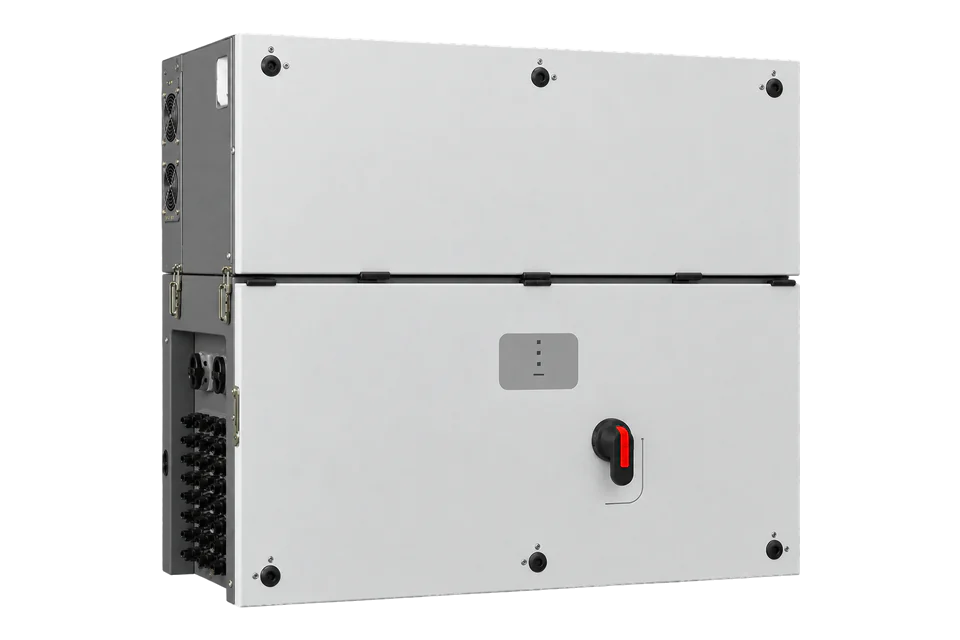
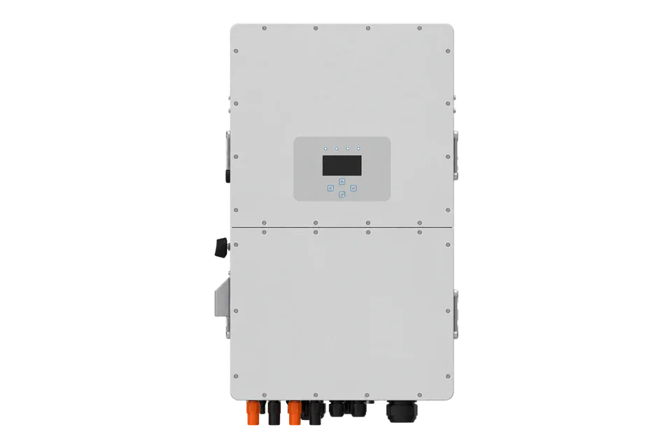
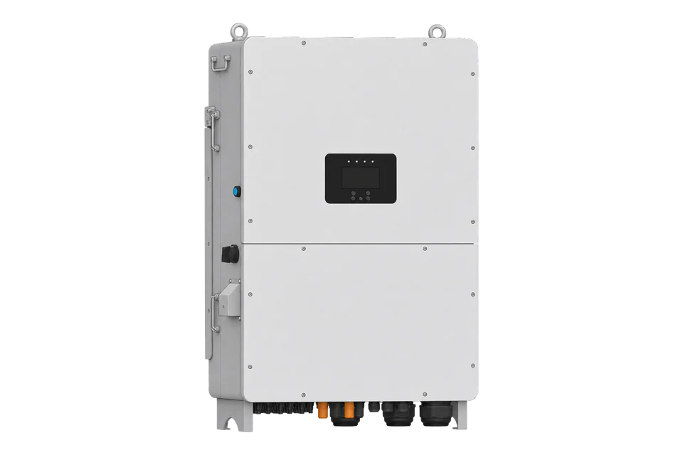
More from FIMER
Sources
- PVS-50/60-TL SunSpec PICS, Rev 3, 7 November 2019 (opens in a new tab)
- PVS-50-TL / PVS-60-TL product manual, Rev F (opens in a new tab) (PDF)
- PVS-50/60-TL datasheet, Rev E (opens in a new tab) (PDF)
- SunSpec Device Information Model Specification 1.1 (opens in a new tab) (PDF)
Further reading
- ApplicationSolar inverter monitoring across a PV fleet
- GuideFIMER PVS-100/120-TL
- ToolModbus data decoder
- ToolModbus RTU CRC
- ToolModbus register address converter
- ToolRS-485 termination and bias
- GuideModbus RS-485 commissioning
- ProtocolModbus devices and register maps
- CategoryInverters and charge controllers
Product names and trademarks belong to their owners. Publication does not imply endorsement or a commercial relationship.