Victron Energy MultiPlus-II
Battery inverter/charger
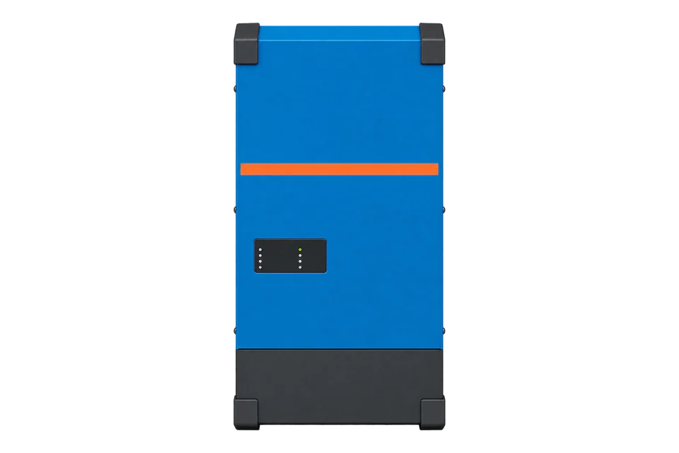
MultiPlus-II is a 3 to 15 kVA battery inverter/charger with a VE.Bus port, used in ESS, backup and off-grid systems. It has no Modbus port of its own. A Victron GX device on its VE.Bus port serves its data over Modbus TCP, and Edge reads the com.victronenergy.vebus registers 3 to 61 at the unit ID the GX lists for that VE.Bus system.
Compatibility
Compatible with EpiSensor Edge over Modbus TCP through a Victron GX device
Victron publishes the GX Modbus TCP register list 3.81, revision 54, with the com.victronenergy.vebus registers for Multis and Quattros, their scale factors and the unit ID mapping. The GX device is the Modbus TCP server; Edge reads it as a client on the site network.
MultiPlus-II 230 V models 12/3000 to 48/15000 on the VE.Bus port of a GX device, read with register list 3.81 revision 54. Site check: confirm the VE.Bus unit ID under Available services on the GX, then compare the first AC input voltage with the GX display. Read-only: ESS setpoints, switch position, current limit and the reset register stay unwritten.
Connect it with

For any MultiPlus-II or parallel and three-phase set of them connected to a Victron GX device
- Wired
- Edge
- Platforms
Models
| Models | Interface | Route into Edge |
|---|---|---|
| MultiPlus-II 230 V 12/3000/120-32, 24/3000/70-32, 48/3000/35-32 | VE.Bus port, two general-purpose com ports, 32 A transfer switch | Through the GX device on VE.Bus. Use the unit ID the GX lists; on a Cerbo GX VE.Bus port the register list's preferred ID is 227. |
| MultiPlus-II 230 V 12/5000/220-50, 24/5000/120-50, 48/5000/70-50, 48/8000/110-100, 48/10000/140-100, 48/15000/200-100 | Same VE.Bus port and register set; 50 A or 100 A transfer switch | Same route. The 8k, 10k and 15k models run in parallel only with an external AC transfer switch, and a parallel or three-phase system appears as one VE.Bus service with per-phase registers. |
| MultiPlus-II GX (built-in GX device) | The GX runs inside the inverter; its internal VE.Bus port is ttyS3 | Point Edge at the inverter's own GX network address. The register list's preferred VE.Bus unit ID for this port is 228. |
Specifications
MultiPlus-II combines an inverter, a charger and a transfer switch with PowerControl and PowerAssist. Up to 6 units run in parallel and three units of one model form a three-phase system; up to 6 three-phase sets can be paralleled.5
- Continuous output at 25 °C
- 3000, 5000, 8000, 10000 and 15000 VA (2400 to 12000 W)5
- Output
- 230 VAC ± 2 %, 50 Hz ± 0.1 % (adjustable to 60 Hz)5
- DC input range
- 12 V: 9.5 to 17 V; 24 V: 19 to 33 V; 48 V: 38 to 66 V5
- Communication
- VE.Bus port for parallel and three-phase operation and system integration; 2 general-purpose com ports5
- Modbus TCP server
- On the GX device, port 502; FC03 and FC04 read, FC06 and FC16 write; access can be set to read-only234
- Environment
- IP22; -40 to +65 °C, fan-assisted cooling; 95 % humidity non-condensing5
Interface
Documented measurements and integration boundaries for MultiPlus-II.
- Address convention: the register list's Address column is the data address placed in the request. Victron's own example reads AC input voltage at unit ID 246 (a CCGX VE.Bus port), address 3, and gets 2302, which divided by 10 is 230.2 V.
- Scaling: divide the raw value by the Scalefactor column. A Scalefactor of 0.1 therefore multiplies by 10: input power raw 250 is 2500 W.
- AC input, unit = VE.Bus service: voltage L1, L2, L3 at 3, 4, 5 (uint16, scale 10, V); current at 6, 7, 8 (int16, scale 10, A; positive flows from mains to the Multi); frequency at 9 to 11 (int16, scale 100, Hz); power at 12, 13, 14 (int16, scale 0.1, W, same sign as current).
- AC output: voltage at 15 to 17 (uint16, scale 10, V); current at 18 to 20 (int16, scale 10, A; positive flows to the load); frequency at 21 (int16, scale 100, Hz); power at 23, 24, 25 (int16, scale 0.1, W).
- DC side: battery voltage at 26 (uint16, scale 100, V DC), battery current at 27 (int16, scale 10, A; positive flows from the Multi into the DC system) and battery temperature at 61 (int16, scale 10, °C).
- Status: phase count at 28, active input at 29 (0 AC input 1, 1 AC input 2, 240 disconnected), VE.Bus state of charge at 30 (uint16, scale 10, %), VE.Bus state at 31 (3 Bulk, 5 Float, 9 Inverting, 10 Power assist, 252 External control), VE.Bus error at 32 and the temperature, low-battery and overload alarms at 34 to 36 (0 OK, 1 warning, 2 alarm).
- Energy counters at 74 to 92 are uint32 with scale 100 in kWh, for example AC-In 1 to AC-out at 74 and battery to AC-out at 90. Victron marks them volatile: they reset when the Multi is switched off and when the GX reboots, so treat them as a running total, not a billing register.
- System totals at unit ID 100 (com.victronenergy.system): AC consumption L1 to L3 at 817 to 819 (W), grid L1 to L3 at 820 to 822 (int16, W, positive from grid), battery power at 842 (int16, W, positive is charging) and battery SoC at 843 (uint16, %).
- Writable VE.Bus registers include 22 (input current limit), 30 (SoC), 33 (switch position), 37 to 41 and 96 to 100 (ESS setpoints) and 62, where any write resets the VE.Bus system. Edge does not write them; control needs the owner's and installer's agreement and is outside this guide.
Assessment
MultiPlus-II 230 V models on the VE.Bus port of a GX device, read with GX Modbus TCP register list 3.81 revision 54. ESS control, configuration and VE.Bus reset are excluded.
- InteroperabilitySupported with conditions
- Victron publishes the register list, scale factors, signs, unit ID mapping and function codes. A GX device is required between the inverter and Edge.123
- AccuracySupported with conditions
- AC input, AC output and DC values are separate per phase with documented signs. Power registers are 16-bit with a 10 W step, and the energy counters are volatile.1
- SecuritySupported with conditions
- Modbus TCP is disabled by default, and the GX Access permissions setting switches clients to read-only. The manual documents no client authentication, so the server must stay on a protected network; with writes allowed it accepts ESS setpoints and a VE.Bus reset.124
- ReliabilitySupported with conditions
- Exception codes 0x0A and 0x0B separate a missing device from an unmapped unit ID, and the GX shows the last Modbus error. The datasheet lists protections for overload, short circuit and battery voltage.25
- RuggednessSupported with conditions
- IP22 with -40 to +65 °C operation and derated output at 40 and 65 °C. The enclosure needs an indoor or protected location.5
- ScalabilitySupported with conditions
- Up to 6 units in parallel and 6 three-phase sets appear as one VE.Bus service. Only one VE.Bus system connects directly to a GX's VE.Bus ports.256
- LifecycleWell supported
- The register list carries a numbered revision history (revision 54 in list 3.81), and the unit ID sheet keeps the older fixed IDs alongside the dynamic scheme.1
Setup
Read AC input voltage, SoC and input power from the VE.Bus service
Register list 3.81 revision 54 puts com.victronenergy.vebus Input voltage phase 1 at address 3 (uint16, Scalefactor 10, V AC), VE.Bus state of charge at 30 (uint16, Scalefactor 10, %) and Input power 1 at 12 (int16, Scalefactor 0.1, W). The voltage reply 2302 is Victron's own example; the other bytes are a synthetic decoder check, not a captured reply.
- Target
- GX device IP address, TCP port 502, unit ID 227 (Cerbo GX VE.Bus port) or the ID shown under Available services
- Voltage request PDU
- 03 00 03 00 01: FC03, address 3, one register
- Voltage response PDU
- 03 02 08 FE: 0x08FE = 2302; 2302 / 10 = 230.2 V AC
- SoC request and synthetic response
- 03 00 1E 00 01 reads address 30; 03 02 02 DF is 735, and 735 / 10 = 73.5 %
- Input power request and synthetic response
- 03 00 0C 00 01 reads address 12; 03 02 FF 06 is int16 -250, and -250 / 0.1 = -2500 W
- Sign
- Negative input power means current flows from the Multi to mains, so -2500 W is feed-in on AC input 1
- Acceptance
- Keep the points when voltage, SoC and input power agree with the GX display at the same time. An exception 0x02 means the address does not exist for that service; 0x0B means the unit ID is not mapped.
Acceptance: A matching voltage confirms the unit ID and address convention; SoC and input power confirm scale and sign. Add AC output, battery and alarm points next.
-
Connect the VE.Bus system to the GX
Connect the first or last MultiPlus-II in the VE.Bus chain to a GX VE.Bus port with a standard RJ45 UTP cable. Do not confuse the VE.Bus ports with the GX Ethernet or VE.Can ports, and leave unused VE.Bus ports open. Only one VE.Bus system connects directly to the GX's own VE.Bus ports.
-
Enable the GX Modbus TCP server
On a Cerbo GX the server sits under Settings > Integrations > Modbus TCP Server; older Venus OS menus place it under Services. Enable Modbus TCP Server, which is disabled by default, and change Access permissions from Write allowed to read-only so a Modbus client cannot change the system. The GX uses the default Modbus TCP port, 502.
-
Find the VE.Bus unit ID
Open Available services on the same menu and note the unit ID next to the VE.Bus service. Since Venus 2.60 unit IDs are assigned dynamically and normally equal the device instance. The register list gives 227 as the preferred ID for a Cerbo GX VE.Bus port, 228 for a MultiPlus-II GX and 246 for a CCGX. Unit ID 100 is the whole system.
-
Read the first VE.Bus block
Create a Modbus TCP connection in Edge to the GX IP address, port 502 and the VE.Bus unit ID. Read with FC03; Victron states FC03 and FC04 behave the same. Registers 1 and 2 do not exist, so start a block at 3. One request from 3 to 36 covers AC input, AC output, battery, state and alarms.
-
Scale, sign and compare
Divide each raw value by its Scalefactor and apply the documented sign: positive input current flows from mains to the Multi, positive battery current flows into the DC system. Compare AC input voltage, output power and VE.Bus SoC with the GX display. If a read returns exception 0x0A, the unit ID is mapped but no VE.Bus device answers; check the cable and the Available services list.
Common questions
- Does the MultiPlus-II have its own Modbus port?
- No. The MultiPlus-II communicates over VE.Bus, Victron's own protocol, and Victron does not allow direct third-party VE.Bus connections. A GX device such as a Cerbo GX reads VE.Bus and acts as the Modbus TCP gateway, selecting the VE.Bus system by unit ID.235
- Which unit ID does a MultiPlus-II use on a Cerbo GX?
- The register list's preferred unit ID for the Cerbo GX VE.Bus port is 227, for a MultiPlus-II GX 228 and for a CCGX 246. Since Venus 2.60 IDs are assigned dynamically, so read the actual ID from Available services. Victron states unit IDs do not change after a reboot.12
- Can I read each unit of a parallel or three-phase system separately?
- No. Victron states units configured for parallel or three-phase work cannot be addressed individually. The VE.Bus service gives system totals and per-phase registers, such as voltage at 3 to 5 and power at 12 to 14.12
- Why did the VE.Bus energy counters drop to zero?
- The register list marks the counters at 74 to 92 as volatile. They reset when the Multi is switched off and when the GX device reboots. Store them in Edge as a running total that can restart.1
Related devices
Sources
- GX Modbus TCP register list 3.81, revision 54 (Field list and Unit ID mapping sheets) (opens in a new tab)
- GX Modbus-TCP manual: unit IDs, function codes and the VE.Bus input voltage example (opens in a new tab)
- Data communication with Victron Energy products, whitepaper: Modbus TCP and VE.Bus (opens in a new tab) (PDF)
- Cerbo GX manual: Configuration, Settings > Integrations > Modbus TCP Server (opens in a new tab)
- MultiPlus-II inverter/charger 230 V datasheet, 3 kVA to 15 kVA (opens in a new tab) (PDF)
- Cerbo GX manual: connecting VE.Bus Multis, Quattros and inverters (opens in a new tab)
- Cerbo GX manual: user interface and network security profile (opens in a new tab)
Further reading
- ApplicationBattery storage performance monitoring
- ApplicationMicrogrid energy management
- GuideVictron Cerbo GX MK2
- GuideVictron Lynx Smart BMS NG
- ToolModbus register decoder
- ToolBattery runtime calculator
- ToolModbus register address converter
- ToolRS-485 termination and bias
- ManufacturerVictron Energy devices
- ProtocolModbus devices and register maps
- CategoryInverters and charge controllers
- CategoryBattery systems and controls
Product names and trademarks belong to their owners. Publication does not imply endorsement or a commercial relationship.