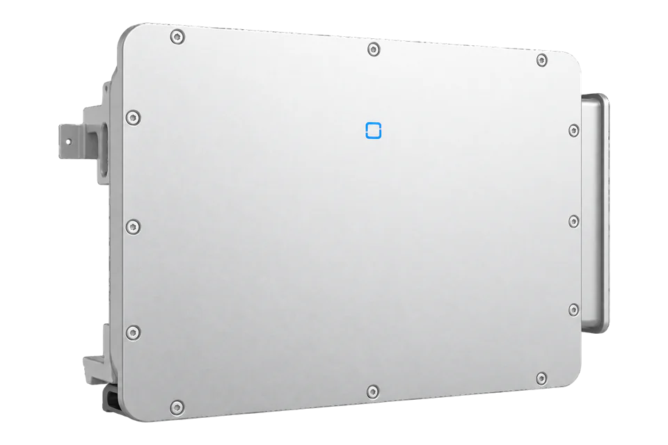
Sungrow SG320HX-20
Utility PV string inverter
A 1500 V DC utility PV inverter with six MPPTs and an 800 V three-phase AC connection. The monitoring connection uses RS485 or a Sungrow PLC data logger; external integration requires the exact model and firmware protocol.
- RS485
Utility PV string inverter
Compatibility
External monitoring requires an exact-model protocol
The manual defines separate RS485 monitoring and tracker ports, plus a PLC connection to a Sungrow data logger. It describes transparent Modbus RTU transmission at the logger, but does not supply an SG320HX-20 register map or establish a native Modbus TCP server. An Edge connection has not been established.
SG320HX-20 under English manual Ver13, October 2024, and global datasheet V8, January 2025. Record the installed firmware, logger model and regional hardware before selecting a monitoring path. SG320HX without the -20 suffix is a separate generation.
Models
| Models | Interface | Route into Edge |
|---|---|---|
| SG320HX-20 | Six MPPTs; up to five input connectors per MPPT; 75 A per MPPT | RS485_1 serves inverter monitoring. The alternative PLC route requires a compatible Sungrow data logger; exact external protocol scope remains to be established. |
| SG320HX, without -20 | V17 datasheet: 12 MPPTs, optional 16; two connectors per MPPT; different current and enclosure specifications | Do not reuse SG320HX specifications, a register map or firmware assumptions for SG320HX-20. |
| SG305HX, SG350HX-20 and SG250HX-20 | Included in the family manual with separate technical data | This guide uses the SG320HX-20 column only. |
Specifications
The -20 suffix identifies a different PV input design. Datasheet V8 specifies six MPPTs with 75 A each, while the older SG320HX V17 datasheet specifies 12 MPPTs with an optional 16-input configuration. Select by the exact nameplate and document revision.23
- PV voltage
- 1500 V maximum; 500–1500 V MPPT range; 550 V startup2
- PV inputs
- Six MPPTs, up to five input connectors each; 75 A maximum input current per MPPT2
- AC output
- 352 kVA at 30°C; 320 kVA at 40°C; 300 kVA at 51°C2
- AC connection
- 800 V nominal, three-phase with protective earth; 640–920 V range2
- Efficiency
- 99.02% maximum; 98.8% European efficiency2
- Monitoring
- RS485_1 monitoring daisy chain or PLC through a Sungrow data logger1
- Tracker communications
- Separate RS485_2 on COM1 pins 7 and 81
- Enclosure and environment
- IP66; -30 to +60°C; forced air cooling; 5000 m maximum, derating above 4000 m2
- Dimensions and weight
- 1148 × 779 × 371 mm; ≤106 kg, with manufacturer-stated ±8% component variation2
Interface
Documented measurements and integration boundaries for SG320HX-20.
- The iSolarCloud local interface shows string voltage and current, MPPT voltage and current, DC power, AC active/reactive/apparent power, line voltage, phase current and grid frequency.
- Operating information includes temperature, insulation resistance, yield and fault/event records. These are documented app functions; their external register addresses, scaling and update intervals are not supplied here.
- Inverter production, a site meter and tracker data serve different purposes. A displayed inverter yield does not establish revenue-meter accuracy or whole-site import and export.
Assessment
SG320HX-20 exact-model manufacturer documentation; external register mapping and firmware applicability remain unresolved.
- InteroperabilityLimited
- RS485 monitoring, serial settings and the PLC logger topology are documented. An exact-model register map and firmware scope are still required for an independent implementation.1
- AccuracyLimited
- The local app documents the electrical quantities and yield information available for operations. The sources do not establish measurement accuracy or externally readable register representations for an independent monitoring client.1
- SecuritySupported with conditions
- The local app uses accounts and supports changing its initial password. External RS485 access requires installation safeguards; the manual does not establish encryption or authenticated external reads.1
- ReliabilitySupported with conditions
- The manual documents operating logs, up to 400 fault entries and 400 event entries, fault diagnostics and maintenance. Continued operation depends on the specified cooling and electrical installation; retention duration through power loss is not established.12
- RuggednessSupported with conditions
- IP66, published temperature and altitude limits, surge protection and a fan-maintenance procedure support utility installations within the stated derating, ventilation and site conditions.12
- ScalabilitySupported with conditions
- The serial interface offers addresses 1–246 and multiple baud rates. Daisy-chain capacity belongs to the selected logger, while polling load and client limits need separate protocol confirmation.1
Setup
-
Record the complete nameplate, regional configuration, installed firmware and logger identity.
Match the six-MPPT SG320HX-20 documentation before designing either the PV strings or communications.
-
Use COM1 RS485_1 for the documented monitoring daisy chain: pins 1 and 2 are A1 positive, pins 3 and 4 are B1 negative, and pins 5 and 6 are shield protective earth.
Refer to manual section 5.9 for the connector drawing and installation procedure.
-
Keep RS485_2 in its tracking-system role: pin 7 is A2 positive and pin 8 is B2 negative.
It is not a spare monitoring port. Existing logger ownership must be resolved before any additional bus controller is connected.
-
The manual limits the RS485 cable to 1000 m and delegates the number of daisy chains and connected devices to the selected logger manual.
Record the actual address and baud rate: section 7.8.4 offers addresses 1–246 and 9600, 19200, 38400, 57600 or 115200 bit/s; it does not establish parity, a register map or safe polling capacity.
-
For PLC, the inverter communicates over its AC output cables with a Sungrow data logger.
Section 5.10 illustrates an MPLC node inside Logger4000 and refers wiring design to the logger manual. PLC is power line communication, not an Ethernet port or an industrial programmable controller.
-
Obtain the current SG320HX-20 protocol with firmware applicability, supported logger forwarding mode, function codes, address base, register widths, byte/word order, scaling and invalid-value handling.
Confirm which device answers each request before selecting an Edge path.
-
After the protocol is established, begin with a bounded read-only check against fresh local app readings.
Active/reactive-power settings, grid functions, boot/shutdown and firmware updates require a separate authorised commissioning procedure.
-
Change the initial local app password and restrict physical and network access to the inverter and logger.
The app account model does not establish authentication or encryption for an external RS485 connection.
Common questions
- Is SG320HX-20 the same as SG320HX?
- No. The -20 datasheet specifies six MPPTs and up to 30 DC inputs. The older SG320HX has 12 MPPTs with an optional 16-MPPT configuration, different current limits and different enclosure dimensions. Use the full model suffix for equipment and protocol selection.23
- Does the inverter provide Modbus TCP?
- The exact-model manual describes RS485 and PLC monitoring. Its PLC section identifies Modbus RTU transparent transmission at the Sungrow logger. It does not establish a native Modbus TCP server in the inverter; any logger Ethernet interface needs its own documentation.1
- Can the tracker port be used for an additional monitoring connection?
- COM1 RS485_2 is assigned to tracking-system communications. The monitoring daisy chain uses RS485_1. Confirm the permitted topology with Sungrow before adding another controller.1
Related devices
Sources
- SG305HX / SG320HX-20 / SG350HX-20 / SG250HX-20 user manual, Ver13, October 2024 (opens in a new tab) (PDF)
- SG320HX-20 global datasheet, V8, 21 January 2025 (opens in a new tab) (PDF)
- SG320HX global datasheet, V17, 21 November 2022 (opens in a new tab) (PDF)
- SG320HX-20 product and document page (opens in a new tab)
Further reading
Product names and trademarks belong to their owners. Publication does not imply endorsement or a commercial relationship.