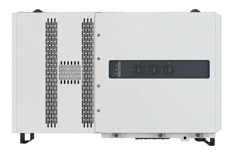
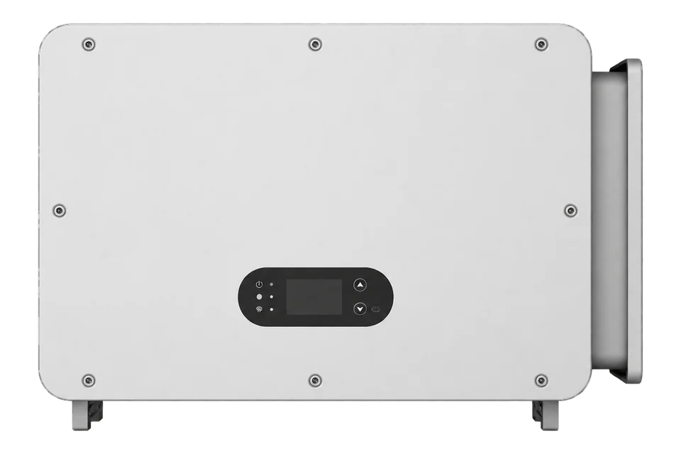
FIMER PVS-100/120-TL
Commercial PV inverter
FIMER documents SunSpec Modbus RTU and TCP for PVS-100/120-TL. Use the exact rating and wiring-box suffix because AC voltage, MPPT count and string monitoring differ. This guide is read-only. Plant control, protection and grid settings stay with the commissioned system.
- Modbus TCP
- Modbus RTU
- SunSpec Modbus
Commercial PV inverter
Compatibility
Compatible through documented SunSpec Modbus
The exact-family product manual documents SunSpec-compliant Modbus RTU and TCP, and FIMER publishes a PICS workbook for the PVS-100/120-TL.
PVS-100-TL and PVS-120-TL only, with the full model suffix, firmware and commissioned interface recorded. Read monitoring data only. Do not change active-power, reactive-power, protection or grid settings.
Connect it with
-
Modbus Interface ZMB-3XFrom €399 ex VAT Configure Modbus Interface
-
Gateway ZGW-20From €899 ex VAT Configure Gateway


For a permitted read-only connection on the inverter LAN
- Modbus
- Edge
- Platforms
When the commissioned RS-485 interface is available for a read-only client
- Modbus
- Edge
- Platforms
Models
| Models | Interface | Route into Edge |
|---|---|---|
| PVS-100-TL | 100 kW at 400 Vac; 2 MPPT or 6 MPPT by suffix | Use the installed suffix and discovered SunSpec models. |
| PVS-120-TL | 120 kW at 480 Vac; 2 MPPT or 6 MPPT by suffix | Do not reuse the PVS-100 electrical limits. |
| SX, SX2, SY and SY2 wiring boxes | Six MPPT variants with differing string-input equipment | Record the full nameplate before assigning points. |
Specifications
PVS-100-TL is rated 100 kW at 400 Vac and PVS-120-TL is rated 120 kW at 480 Vac. The product family has two- and six-MPPT wiring-box variants, so the family name alone is insufficient for array or point design.13
Interface
Documented measurements and integration boundaries for PVS-100/120-TL.
- Inverter identity and firmware from the implemented SunSpec common model.
- AC power, voltage, current, frequency and energy where returned by the installed SunSpec model set.
- DC power and operating state where the installed variant and firmware expose them.
Assessment
Exact PVS-100/120-TL suffix and firmware, using documented SunSpec Modbus only.
- InteroperabilitySupported with conditions
- Exact-family SunSpec RTU and TCP plus a PICS are published; model and firmware discovery remain required.12
- AccuracySupported with conditions
- Electrical measurements and identity models are documented, while available points depend on the installed suffix and firmware.12
- SecurityLimited
- The local Modbus paths do not provide transport encryption or peer authentication, so network isolation and read-only enforcement are required.1
- ReliabilitySupported with conditions
- Environmental limits and communications hardware are published; polling recovery and coexistence need site testing.13
- RuggednessSupported with conditions
- IP66 and installation limits are published for the family, subject to the exact variant and installation method.3
- ScalabilitySupported with conditions
- Ethernet daisy-chain and addressed serial operation are documented, but client roles and segment loading need an engineered site plan.1
Setup
-
Identify the exact inverter
Record PVS-100 or PVS-120, the complete wiring-box suffix, serial number and firmware. Confirm the site AC voltage and MPPT count against the nameplate.
-
Preserve plant control
Record the existing logger, plant controller and grid settings. Use a read-only client and do not enable or exercise power-control functions.
-
Choose one documented interface
For TCP, use a permitted protected LAN endpoint. For RTU, confirm slave mode, address, serial framing and termination without displacing the current bus master.
-
Discover before decoding
Read the SunSpec signature and model headers, then use only models listed by the inverter and applicable to its firmware. Do not paste offsets from another ABB or FIMER family.
-
Validate measurements
Compare identity, operating state and one live power value with the inverter display or commissioned monitoring system before expanding the point list.
Common questions
- Does every PVS-100/120-TL have six MPPTs?
- No. FIMER publishes both two- and six-MPPT wiring-box variants. The complete suffix determines the input topology.13
- Does this guide permit inverter control?
- No. It covers read-only SunSpec monitoring. Active and reactive power commands, protection and grid settings remain outside this integration.1
Related devices
Sources
- PVS-100/120-TL product manual, Rev G (opens in a new tab) (PDF)
- PVS-100/120 SunSpec PICS, Rev 005 (opens in a new tab)
- PVS-100/120-TL Datasheet, Rev D (opens in a new tab) (PDF)
Further reading
Product names and trademarks belong to their owners. Publication does not imply endorsement or a commercial relationship.