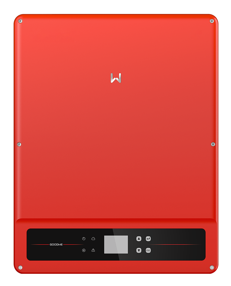
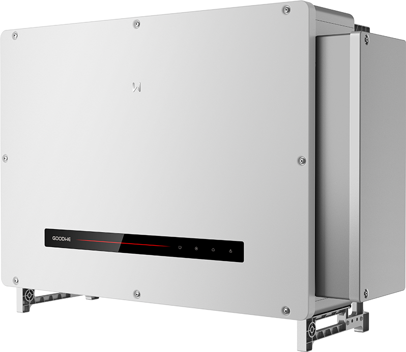
GoodWe GW100K-ET-G10
Commercial hybrid inverter
A 100 kW three-phase hybrid inverter with eight MPPTs and two high-voltage battery inputs. This guide covers its documented EMS RS-485 monitoring path.
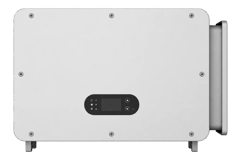
- Modbus RTU
Commercial hybrid inverter
Compatibility
Compatible through Modbus RTU
GoodWe documents the EMS RS-485 connection and publishes a read-only monitoring table within its third-party EMS protocol. This is a documented integration path, not a physical qualification or downloadable Edge template.
GW100K-ET-G10 in the July 2026 EMEA datasheet, ET 50–100kW user manual V1.2 of 2 July 2026, and Third-Party EMS Protocol MODBUS V1.1.1 linked by GoodWe for this family. No minimum firmware version is specified in the retained protocol. Confirm installed firmware and map availability during commissioning; older ET, ET G2, BT and other regional variants are separate scopes.
Connect it with
-
Modbus Interface ZMB-3XFrom €399 ex VAT Configure Modbus Interface
-
Gateway ZGW-20From €899 ex VAT Configure Gateway


For local monitoring through the dedicated EMS communication port
- Modbus
- Edge
- Platforms
Models
| Models | Interface | Route into Edge |
|---|---|---|
| GW100K-ET-G10, EMEA | 100 kW, three-phase; eight MPPTs; two battery inputs | This exact model and the documented EMS RTU route are the scope of the worked read. |
| GW80K-ET-G10 / GW99.99K-ET-G10 | Related regional models with different power ratings | Use their own rated limits and identity; a shared document does not make these the same device. |
| Legacy ET / ET G2 / BT / other regions | Different generations, topology or regional specifications | Do not carry over this map or connection procedure without matching manufacturer documentation. |
Specifications
GW100K-ET-G10 is the 100 kW selection in the EMEA ET 80–100kW hybrid range. It has eight MPPTs with two PV strings per MPPT and two high-voltage battery inputs. The July 2026 regional datasheet specifies 300–800 V battery operation and 110 A maximum continuous charge or discharge current per battery input. These are inverter limits, not permission to use an arbitrary battery: the battery system and BMS must also be compatible. Backup operation needs the separately specified STS box or cabinet.13
- Regional scope
- GW100K-ET-G10, EMEA July 2026 datasheet3
- Nominal AC power
- 100 kW, three-phase 220/380, 230/400 or 240/415 V3
- PV inputs
- Eight MPPTs, two strings per MPPT; 1000 V maximum input3
- PV voltage boundary
- 160–950 V MPPT operating range; 950–1000 V enters standby under datasheet footnote 13
- Battery inputs
- Two; 300–800 V operating range; 110 A maximum continuous current per input3
- Local EMS connection
- Port E: pin 1 RS485-A1, pin 2 RS485-B11
- Serial defaults
- 9600 baud, 8 data bits, no parity, 1 stop bit; address 247 before configuration2
- Protection and environment
- IP66; -35 to +60 °C; stated maximum operating altitude 4000 m3
- Backup topology
- Requires the specified separate STS box or cabinet3
Interface
Documented measurements and integration boundaries for GW100K-ET-G10.
- PV input voltage and current with the scaling stated for each register.
- Individual MPPT power, distinguished from total inverter and grid power.
- Battery and system operating status where supported by the installed firmware.
- Device serial number and external model name for identity checks.
Assessment
GW100K-ET-G10 in the July 2026 EMEA datasheet, ET 50–100kW user manual V1.2 of 2 July 2026, and Third-Party EMS Protocol MODBUS V1.1.1 linked by GoodWe for this family. No minimum firmware version is specified in the retained protocol. Confirm installed firmware and map availability during commissioning; older ET, ET G2, BT and other regional variants are separate scopes.
- InteroperabilitySupported with conditions
- The dedicated EMS RTU interface and monitoring table are documented; model, installed settings and firmware still bound the integration.12
- AccuracySupported with conditions
- The protocol states types, widths, scales and read cycles. It does not establish billing-meter accuracy for these inverter measurements.2
- SecurityNot yet assessed
- The RTU documents do not establish authentication, encryption or a guaranteed security-maintenance period.2
- ReliabilityNot yet assessed
- No measured availability or historical backfill contract is established for this monitoring path.12
- RuggednessSupported with conditions
- The regional datasheet specifies IP66 and -35 to +60 °C; installation limits and operating derating still apply.3
- ScalabilitySupported with conditions
- Addressed RTU monitoring supports integration, but an existing EMS must retain bus ownership and point read cycles must be respected.12
- LifecycleNot yet assessed
- Current dated documentation is available, without a stated guaranteed product support lifetime.1
Setup
Read PV and signed AC power
The manufacturer’s monitoring table defines 35103 as a one-register U16 PV1 voltage, scale factor 10, in volts. The read cycle is one second.
- Read PDU
- 03 89 1F 00 01: FC03, literal address 35103 (0x891F), quantity 1.
- Synthetic response data
- 18 38 represents unsigned 6200. Divide by 10 to obtain 620.0 V.
- Identity first
- Read serial number 35003 across all eight registers; external model name 35060 spans sixteen registers.
- RTU envelope
- The client adds the configured address and standard Modbus CRC16. The PDU shown is not a complete RTU frame.
- PV1 current and MPPT power
- FC03 at literal address 35103, quantity 4: PDU 03 89 1F 00 04. This reads PV1 voltage (U16 ÷10 V), PV1 current at 35104 (U16 ÷10 A), and MPPT1 power at 35105–35106 (U32 in W). Synthetic words 1838 0064 0000 1838 give 620.0 V, 10.0 A and 6200 W. Combine the two power words most significant first; do not divide the watt value by 10 or treat it as Float32.
- Signed inverter active power
- FC03 address 35137, quantity 2: PDU 03 89 41 00 02 reads Total Inverter Power, signed S32, scale 1 W. Synthetic 00 00 30 39 gives 12345 W; FF FF CF C7 gives -12345 W. Join both words before signed decoding. The map lists a one-second read cycle; retain sign and compare a fresh value with the local interface.
- Inverter versus grid power
- AC Active Power at 35139 is a separate S32 pair, PDU 03 89 43 00 02. GoodWe defines it as meter power when meter communication works, but inverter on-grid-port power when that connection fails. It is therefore not an unconditional site import/export reading. Track meter communication and preserve the commissioned sign convention before using it in a site balance.
Acceptance: Use the public V1.1.1 map as a best-effort starting point and compare fresh PV voltage/current and signed inverter power with the local interface. The payloads above are synthetic decoder examples. Keep monitoring reads separate from EMS-mode, battery-dispatch and protection writes.
-
Identify model, region and firmware
GW100K-ET-G10 in the July 2026 EMEA datasheet, ET 50–100kW user manual V1.2 of 2 July 2026, and Third-Party EMS Protocol MODBUS V1.1.1 linked by GoodWe for this family. No minimum firmware version is specified in the retained protocol. Confirm installed firmware and map availability during commissioning; older ET, ET G2, BT and other regional variants are separate scopes.
-
Use the EMS port
Follow the installation manual for the dedicated EMS port E, pin 1 RS485-A1 and pin 2 RS485-B1. Verify bus ownership before adding a client. Do not attach the polling client to the battery CAN, meter or transfer-switch communication connections.
-
Match the configured serial settings
The protocol specifies 9600 baud with 8 data bits, no parity and one stop bit. Addresses are 1–247, with 247 as the factory default. Read the installed setting instead of assuming a default address is still valid.
-
Begin with identity and one monitoring read
FC03 at literal address 35103, quantity 4: PDU 03 89 1F 00 04. This reads PV1 voltage (U16 ÷10 V), PV1 current at 35104 (U16 ÷10 A), and MPPT1 power at 35105–35106 (U32 in W). Synthetic words 1838 0064 0000 1838 give 620.0 V, 10.0 A and 6200 W. Combine the two power words most significant first; do not divide the watt value by 10 or treat it as Float32.
-
Check scaling and freshness
FC03 address 35137, quantity 2: PDU 03 89 41 00 02 reads Total Inverter Power, signed S32, scale 1 W. Synthetic 00 00 30 39 gives 12345 W; FF FF CF C7 gives -12345 W. Join both words before signed decoding. The map lists a one-second read cycle; retain sign and compare a fresh value with the local interface.
-
Keep the first integration read-only
Use only the monitoring table. Do not copy the protocol’s third-party control sequences, heartbeat settings, charge/discharge commands or RTC writes into a monitoring client. The protocol includes inconsistent CRC wording beside CRC frame fields; use standard Modbus RTU CRC16 through the client, never disable frame integrity checking.
Common questions
- Is this a guide for the older 10 kW ET?
- No. GW100K-ET-G10 belongs to the current commercial platform. Legacy ET and ET G2 ratings and protocol maps must be matched separately.13
- Does WiFi or SEMS+ access provide this local Modbus connection?
- No. Vendor remote monitoring and the dedicated EMS RS-485 connection are different paths. The datasheet also lists Modbus TCP, but this guide does not infer TCP settings from a cloud connection.13
- Can I add this client beside an existing EMS?
- Not as a competing master on the same serial bus. Coordinate with the existing EMS owner or obtain measurements through its supported interface. Meter, battery and transfer-switch communication are separate connections with their own roles.1
- Why does the guide avoid control registers?
- The published document contains operating-mode and battery dispatch commands as well as measurements. Reading voltage does not validate their safety or the interaction with site controls. This guide stays within the read-only monitoring table.2
- Is there a documented minimum firmware version?
- The retained V1.1.1 simplified protocol does not state a minimum inverter firmware. Record the installed firmware and verify the intended monitoring entries during commissioning rather than inventing a universal firmware floor.2
Related devices

Sources
- ET 50–100kW user manual V1.2, 2 July 2026 (opens in a new tab) (PDF)
- Third-Party EMS Protocol MODBUS V1.1.1, simplified version (opens in a new tab) (PDF)
- ET 80–100kW EMEA datasheet, July 2026 (opens in a new tab) (PDF)
- ET 50–100kW solution manual V1.3, June 2026 (opens in a new tab) (PDF)
Further reading
- GuideSungrow SH10RT
- GuideSolis 50 kW commercial hybrid: monitoring access and port roles
- ToolModbus data decoder
- ToolPV string sizing
- ToolModbus register address converter
- ToolRS-485 termination and bias
- ManufacturerGoodWe devices
- ProtocolModbus devices and register maps
- CategoryInverters and charge controllers
Product names and trademarks belong to their owners. Publication does not imply endorsement or a commercial relationship.