GoodWe GW10K-ET-20
Hybrid inverter
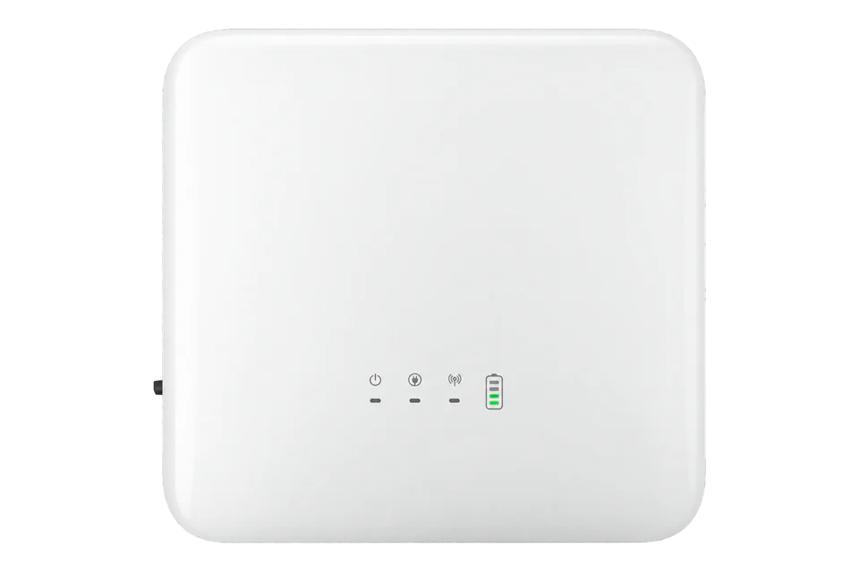
The 10 kW ET G2 combines three PV trackers, a high-voltage battery connection and three-phase backup output. It differs from both the original ET and the low-voltage ET-L family. Its separate meter, battery and EMS connections have different jobs: an RS-485 connector used by the battery or meter is not a spare monitoring port.
- Modbus RTU
Hybrid inverter
Compatibility
Documented monitoring interface with conditions
Use the manufacturer’s local monitoring interface and an exact installed-device mapping. No physical validation or prepared Edge import is claimed.
Exact GW10K-ET-20, ET G2 high-voltage three-phase hybrid, using the global ET G2 datasheet V2.1 and current residential solution manual V2.2 dated 30 September 2026. The original GW10K-ET, low-voltage ET-L and commercial ET G10 platforms are separate. GoodWe publishes a hybrid-family Modbus EMS protocol; confirm its applicability and available fields for the installed inverter and communication firmware. No exact-model register import or physical integration is supplied. Third-party EMS is not supported in the documented parallel arrangement.
Connect it with
-
Modbus Interface ZMB-3XFrom €399 ex VAT Configure Modbus Interface
-
Gateway ZGW-20From €899 ex VAT Configure Gateway


A single-inverter installation has the applicable EMS interface and confirmed firmware protocol
- Modbus
- Edge
- Platforms
Models
| Models | Interface | Route into Edge |
|---|---|---|
| GW10K-ET-20 | ET G2, three-phase, high-voltage battery, three MPPTs | Qualified read-only EMS integration on the documented single-inverter arrangement. |
| GW6000-ET-20 and GW8000-ET-20 | ET G2 variants with two MPPTs and 30 A battery current rating | Do not use the 10 kW model’s three-tracker or 40 A specifications. |
| Original GW10K-ET | Earlier ET hardware generation | The missing -20 suffix is meaningful; obtain that generation’s documents. |
| ET LV / ET-L and ET G10 | Different battery-voltage or commercial platforms | Not covered by this ET G2 electrical scope or assumed to share a ready-made map. |
Specifications
The headline 10 kW is the nominal AC output, not the maximum PV-array or battery charging figure. Size each side separately and apply the datasheet’s regional footnotes, battery compatibility list and installation limits.2
- Nominal AC output
- 10,000 W, three-phase 380/400 V, 3L/N/PE, 50/60 Hz.2
- PV inputs
- Three MPPTs, one string per tracker; 16 A operating and 24 A short-circuit current per MPPT.2
- PV voltage
- 1000 V absolute input maximum; 120–850 V MPPT range. The datasheet states 950 V maximum operating voltage for the 1000 V system.2
- PV input-power figure
- 16,000 W for the global GW10K-ET-20 column; the oversizing figure is not a continuous 16 kW AC output rating.2
- Battery
- One high-voltage lithium-ion interface, 150–720 V range, 500 V nominal; maximum continuous charge/discharge current 40 A.2
- Battery conversion limits
- Maximum charging power 15,000 W and discharging power 11,000 W in this datasheet; actual output depends on the approved battery and operating conditions.2
- Backup
- 10,000 VA nominal; up to 18,000 VA for 60 seconds without grid, only with sufficient PV and battery power.2
- Mounting and environment
- Wall mounting, 496 × 460 × 221 mm, 25 kg; IP66, −35 to +60 °C with installation/derating conditions.2
- Protection options
- Type II surge protection on DC and AC sides; AFCI 3.0 is optional, not guaranteed on every installed order.2
Interface
Documented measurements and integration boundaries for GW10K-ET-20.
- PV, battery, inverter and grid-meter values represent distinct energy boundaries; retain the source of each measurement.
- GoodWe’s hybrid-family EMS protocol defines read-only operating and fault data, including identity and measurements. Confirm exact firmware coverage before creating points.
- The external model-name field is distinct from the shorter field marked only for EH/ET PLUS in the protocol; do not use a partial model string to qualify ET G2 automatically.
- No model-specific address, energy multiplier or template is asserted by this guide.
Assessment
Exact GW10K-ET-20, ET G2 high-voltage three-phase hybrid, using the global ET G2 datasheet V2.1 and current residential solution manual V2.2 dated 30 September 2026. The original GW10K-ET, low-voltage ET-L and commercial ET G10 platforms are separate. GoodWe publishes a hybrid-family Modbus EMS protocol; confirm its applicability and available fields for the installed inverter and communication firmware. No exact-model register import or physical integration is supplied. Third-party EMS is not supported in the documented parallel arrangement.
- InteroperabilitySupported with conditions
- Dedicated third-party EMS RS-485 and a public hybrid-family Modbus protocol are documented; exact firmware mapping and single-inverter scope still apply.34
- AccuracySupported with conditions
- Separate PV, battery and grid-meter roles support energy monitoring; validate signs and boundaries against the manufacturer system.3
- SecurityNot yet assessed
- The retained EMS protocol does not establish authenticated or encrypted protection for its serial reads.4
- ReliabilitySupported with conditions
- Fault status, local commissioning and multiple electrical protection functions are documented; unavailable telemetry needs explicit handling.23
- RuggednessSupported with conditions
- IP66, wall mounting and the stated ambient range are documented; regional installation and derating conditions remain applicable.2
- ScalabilitySupported with conditions
- The product supports parallel expansion, but that configuration excludes the documented third-party EMS path.3
Setup
Read PV and signed AC power
The manufacturer’s monitoring table defines 35103 as a one-register U16 PV1 voltage, scale factor 10, in volts. The read cycle is one second.
- Read PDU
- 03 89 1F 00 01: FC03, literal address 35103 (0x891F), quantity 1.
- Synthetic response data
- 18 38 represents unsigned 6200. Divide by 10 to obtain 620.0 V.
- Identity first
- Read serial number 35003 across all eight registers; external model name 35060 spans sixteen registers.
- RTU envelope
- The client adds the configured address and standard Modbus CRC16. The PDU shown is not a complete RTU frame.
- PV1 current and MPPT power
- FC03 at literal address 35103, quantity 4: PDU 03 89 1F 00 04. This reads PV1 voltage (U16 ÷10 V), PV1 current at 35104 (U16 ÷10 A), and MPPT1 power at 35105–35106 (U32 in W). Synthetic words 1838 0064 0000 1838 give 620.0 V, 10.0 A and 6200 W. Combine the two power words most significant first; do not divide the watt value by 10 or treat it as Float32.
- Signed inverter active power
- FC03 address 35137, quantity 2: PDU 03 89 41 00 02 reads Total Inverter Power, signed S32, scale 1 W. Synthetic 00 00 30 39 gives 12345 W; FF FF CF C7 gives -12345 W. Join both words before signed decoding. The map lists a one-second read cycle; retain sign and compare a fresh value with the local interface.
- Inverter versus grid power
- AC Active Power at 35139 is a separate S32 pair, PDU 03 89 43 00 02. GoodWe defines it as meter power when meter communication works, but inverter on-grid-port power when that connection fails. It is therefore not an unconditional site import/export reading. Track meter communication and preserve the commissioned sign convention before using it in a site balance.
Acceptance: Use the public V1.1.1 map as a best-effort starting point and compare fresh PV voltage/current and signed inverter power with the local interface. The payloads above are synthetic decoder examples. Keep monitoring reads separate from EMS-mode, battery-dispatch and protection writes.
-
Confirm the -20 generation
Read GW10K-ET-20 from the nameplate and record inverter, ARM/DSP and communication-module firmware. Use the corresponding ET G2 documents and regional battery compatibility list. Do not substitute original ET or ET-L electrical ratings.
-
Record the complete power system
Confirm PV tracker allocation, approved battery type, grid meter/CT arrangement and backup circuits with the installer. Verify the manufacturer system’s power directions before adding a separate monitoring client.
-
Check the parallel-system restriction
The current solution manual states that third-party EMS devices are not supported in parallel scenarios. Do not add a second EMS master to a parallel system or assume a shared connector is unused.
-
Use the EMS port, not the meter or battery port
Follow the exact model’s terminal diagram. The manual distinguishes EMS RS-485, meter RS-485, battery RS-485/CAN and parallel CAN/BUS. Connector shape alone does not identify Ethernet or a general-purpose monitoring interface.
-
Use the documented read settings
Use the public V1.1.1 protocol as the starting map: FC03, 9600 bit/s, 8N1, address range 1–247 (factory default 247). Record the actual site address and firmware. Begin with serial number 35003 across eight registers and model name 35060 across sixteen, then the PV block below.
-
Validate each field without enabling dispatch
Use the public V1.1.1 map as a best-effort starting point and compare fresh PV voltage/current and signed inverter power with the local interface. The payloads above are synthetic decoder examples. Keep monitoring reads separate from EMS-mode, battery-dispatch and protection writes.
Common questions
- Can I use the meter RS-485 connection for Edge?
- That port has a defined role in the inverter’s energy-management system. Use the documented EMS interface after checking the exact installation. Do not add another master to the meter bus or disconnect the meter to make space.3
- Can a parallel ET G2 installation also use a third-party EMS?
- The retained V2.2 manual explicitly excludes third-party EMS and charging-pile connections in the parallel arrangement. Obtain a manufacturer-supported architecture rather than assume the single-inverter EMS path applies.3
- Does the optional network dongle guarantee Modbus TCP?
- No universal dongle or firmware promise is made here. The hybrid-family protocol describes TCP port 502 and enabling Modbus through SEMS+, but the actual communication module, compatible firmware and site settings must be established separately. This guide’s connection path is the dedicated EMS RS-485 interface.4
- Why is there no energy-register example?
- The public protocol covers several hybrid platforms and some entries have model-specific notes. Exact ET G2 availability, representation and unavailable-value behaviour must be confirmed before a point is advertised as ready to import.4
Related devices
Sources
- GoodWe ET G2 product and download page (opens in a new tab)
- ET G2 global datasheet V2.1, 8 August 2025 (opens in a new tab)
- Residential smart-inverter solution manual V2.2, 30 September 2026 (opens in a new tab)
- Third-party EMS Modbus protocol V1.1.1, simplified edition (opens in a new tab)
Further reading
Product names and trademarks belong to their owners. Publication does not imply endorsement or a commercial relationship.