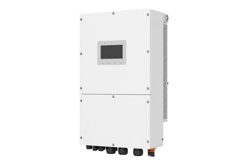
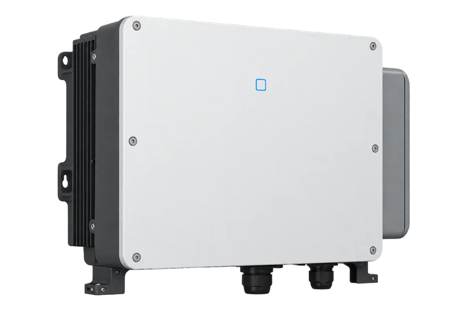
Solis S6-EH3P50K-H
Commercial hybrid inverter
A 50 kW three-phase hybrid inverter with four MPPTs, two high-voltage battery ports and a separate backup output. Solis now publishes its hybrid Modbus map. Use the external EMS role or a supported logger, then compare the first frequency, SOC and PV power reads with the local display.
- Modbus RTU
- Modbus TCP
- CAN
Commercial hybrid inverter
Compatibility
Public hybrid map; Edge import remains site-specific
The European manual identifies an EMS connection for third-party RS-485 devices. Solis now supplies a public hybrid protocol with addresses, data formats and timing; its device-type table covers S6 high-voltage 29.9–150 kW units. This guide supplies a best-effort monitoring procedure, not a tested Edge import.
European S6-EH3P50K-H under manual V1.2, 21 August 2025, 380/400 V three-phase with neutral. Use protocol Ver3.5 as the starting point and compare initial reads with the display. Excludes LV, 21A, ND/AU and larger K10 electrical variants; keep meter, BMS and inverter-master connections in their assigned roles.
Models
| Models | Interface | Route into Edge |
|---|---|---|
| S6-EH3P50K-H, European scope | 50 kW; four MPPTs; 150–800 V battery range | Use the third-party EMS role or a supported logger; retain the exact-model wiring and commissioned bus ownership. |
| S6-EH3P30K-H-LV, 21A, ND and AU versions | Different voltage/current or regional hardware scope | Do not transfer the specifications, firmware assumptions or register layout from this guide. |
Specifications
The global V3.8 datasheet and European V1.2 manual establish a 50 kW commercial hybrid scope. The datasheet distinguishes 100 kW recommended PV array capacity from 96 kW maximum usable PV power; neither is a 100 kW AC output rating.12
- AC rating
- 50 kW, 380/400 V three-phase with neutral2
- PV inputs
- Four MPPTs, eight strings; 1000 V maximum DC2
- PV power
- 100 kW recommended array; 96 kW maximum usable input2
- Battery
- Two ports; 150–800 V; 70 A per port in retained V3.8 datasheet2
- Backup
- 50 kW rated; 1.6 times overload for 2 seconds2
- Enclosure
- IP66; -25 to +60°C; intelligent fan cooling2
- Dimensions and weight
- 530×880×290 mm; 73 kg2
Interface
Documented measurements and integration boundaries for S6-EH3P50K-H.
- The inverter provides local PV, battery and AC operating information through its screen and supported monitoring arrangement.
- The public hybrid map gives FC04 frequency 33094, battery 1 SOC 33139, PV power 33057–33058 and inverter active power 33079–33080. PV, inverter AC, battery and site-meter values have different boundaries.
- Battery BMS measurements, site meter readings and inverter output are different sources; preserve those identities when designing a monitoring map.
Assessment
European S6-EH3P50K-H selection and best-effort monitoring using public hybrid protocol Ver3.5. No installed Edge import or physical acceptance is claimed.
- InteroperabilitySupported with conditions
- The public hybrid map documents S6 high-voltage family types, RTU parameters and operational reads; the exact installation retains its EMS role.156
- AccuracySupported with conditions
- Operational registers have published type, unit and high-word-first decoding. Separate PV, inverter AC, BMS and site-meter boundaries; confirm supported points by display comparison.5
- SecuritySupported with conditions
- Solis recommends VLAN/firewall access restrictions for Modbus TCP. The logger setup uses a local password; polling encryption and separate read-only roles are not specified.46
- ReliabilitySupported with conditions
- The protocol defines query timing, error replies and zero responses for unimplemented registers. Use freshness timestamps and inverter diagnostics for recovery checks.15
- RuggednessSupported with conditions
- IP66 enclosure with published ambient limits and active cooling supports outdoor electrical installations within those limits.2
- ScalabilityLimited
- Published address settings and query intervals support a bounded polling plan; the generic protocol currently permits one TCP connection, not an unlimited multi-client service.5
Setup
-
Identify the inverter and external port
Use the exact S6-EH3P50K-H nameplate and European V1.2 manual. The communications table identifies EMS as the third-party external RS-485 connection; its drawing assigns A to RJ45 pin 5 and B to pin 4. The optional-port section also describes an inverter-master function. Select the external EMS role and preserve existing ownership before adding a polling master. Meter, BMS and parallel connectors remain separate; COM is the logger connection.
-
Choose RTU or the supported logger
The public protocol gives RTU starting values of address 1, 9600 baud, 8 data bits, no parity and 1 stop bit; match installed settings. Solis describes the dedicated S6 RTU port as separate from cloud monitoring. For TCP, the developer platform identifies S2-WL-ST firmware 100101B4 or later; use its assigned LAN IP and port 502. The logger SOP says enabling TCP disconnects that logger from SolisCloud, so retain the dedicated RTU route when cloud continuity matters. Do not treat the inverter RJ45 RS-485 connector as Ethernet.
-
Record identity and the first read
Use the public Energy Storage Inverter protocol Ver3.5, revised July 2026, as a best-effort starting point. FC04 input register 35000 identifies the family: Appendix 1 lists 0x2073/0x2173/0x2273 for S6 high-voltage 29.9–150 kW units. Read the displayed model and firmware alongside it. The document’s decimal numbers are wire addresses, confirmed by its 33001 example using hex 80 E9; do not remove a 30000 prefix or subtract one. Space query frames by more than 300 ms; one-second polling is a practical starting interval.
-
Read frequency and battery SOC
FC04 register 33094 (hex 0x8146), quantity 1, is grid frequency as U16 × 0.01 Hz. Request PDU: 04 81 46 00 01. Read bytes high first: synthetic data 13 88 is 5000, giving 50 Hz. Battery 1 SOC is FC04 33139 (0x8173), quantity 1, U16 in 1%: PDU 04 81 73 00 01 and data 00 4B give 75%. Compare these with the local inverter and BMS display before expanding.
-
Expand PV and inverter measurements
FC04 33057–33058 is total PV input power, U32 in W, high word first. PDU 04 81 21 00 02; synthetic data 00 00 30 39 gives 12345 W. FC04 33079–33080 is inverter/rectifier active power, S32 in W with the same order; 00 00 30 39 gives +12345 W and FF FF CF C7 gives -12345 W. Establish the installed direction against the display; this is inverter AC power, not whole-site import/export. Add total PV energy 33029–33030 U32 in kWh, today’s PV energy 33035 U16 × 0.1 kWh, and PV1 voltage/current 33049/33050 U16 × 0.1 V/A as needed.
-
Keep zero, faults and freshness distinct
The protocol says an unimplemented register can return 0000 without an exception. Treat an unexplained zero as a point-support check rather than proof of no energy flow. Retain timestamps and mark timeouts or invalid replies stale. Read status 33095 with fault detail 33070 using the protocol appendix; compare the exact alarm with the inverter display. Battery modes, export limits and grid settings remain with the commissioned control system.
Related devices
Sources
- European S6-EH3P user manual V1.2, August 2025 (opens in a new tab) (PDF)
- S6-EH3P global datasheet V3.8 (opens in a new tab) (PDF)
- Current S6-EH3P commercial hybrid product page (opens in a new tab)
- S2-WL-ST Modbus TCP communication and cloud boundary (opens in a new tab)
- Energy storage inverter communication protocol Ver3.5, July 2026 revision (opens in a new tab) (PDF)
- Public grid and hybrid Modbus tables, updated 8 October 2026 (opens in a new tab)
- SolisCloud developer platform: Modbus and direct communication (opens in a new tab)
Further reading
- ApplicationMulti-site energy monitoring
- ToolSolar PV string sizing
- GuideGoodWe GW100K-ET-G10 integration
- ToolModbus register address converter
- ToolModbus data decoder
- ToolRS-485 termination and bias
- GuideModbus RS-485 commissioning
- ProtocolModbus devices and register maps
- CategoryInverters and charge controllers
Product names and trademarks belong to their owners. Publication does not imply endorsement or a commercial relationship.