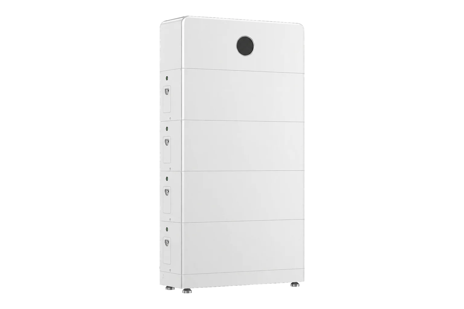
GoodWe GW10K-EHA-G20
Single-phase hybrid inverter
GW10K-EHA-G20 is the 10 kW single-phase ESA power module. The August 2026 datasheet lists four PV trackers, a 350–550 V battery interface and distinct 10 kW AC, 13.5 kW maximum battery-charge and 11 kW discharge limits. The July 2026 system manual identifies a third-party EMS connector separately from the meter and battery wiring; its technical table lists Modbus RTU/TCP. An exact firmware-matched measurement map and interface configuration are still needed before reading values.
- Modbus RTU
- Modbus TCP
Single-phase hybrid inverter
Compatibility
Documented third-party EMS interface with conditions
The exact ESA G20 manual includes GW10K-EHA-G20 and identifies port G for third-party EMS. GoodWe’s public V1.1.1 hybrid protocol includes ESA in its family list and supplies monitoring fields. Use it as a best-effort starting map on the commissioned EMS interface, with identity and display comparison; optional TCP hardware is a separate choice.
EMEA GW10K-EHA-G20 single-phase ESA G20 power module with approved GoodWe battery and meter/CT arrangement. Datasheet V2.1, 31 August 2026 and system manual V1.8, 28 July 2026. GW9.999K-EHA-G20, BHA AC-coupled and ETA three-phase models are separate. Read-only monitoring; no dispatch, grid-limit or battery-mode writes.
Connect it with
-
Modbus Interface ZMB-3XFrom €399 ex VAT Configure Modbus Interface
-
Gateway ZGW-20From €899 ex VAT Configure Gateway
-
Evaluation Gateway on a Raspberry Pi Edge with one device licensedFree Set up Evaluation Gateway on a Raspberry Pi


The installed single-phase GW10K-EHA-G20 has an available manufacturer-approved EMS port and matching RTU protocol
- Modbus
- Edge
- Platforms
Models
| Models | Interface | Route into Edge |
|---|---|---|
| GW10K-EHA-G20 | Single-phase 10 kW ESA G20 with four MPPTs | Qualify the dedicated EMS route and exact firmware map before read-only monitoring. |
| GW9.999K-EHA-G20 | Separate 9.999 kW grid rating in the same datasheet | Do not round its regional grid rating to the 10 kW ordering code. |
| GW10K-BHA-G20 / GW10K-ETA-G20 | AC-coupled / three-phase families | Do not transfer ESA EHA wiring or battery/PV ratings. |
Specifications
- Model scope
- GW10K-EHA-G20, single-phase 220/230/240 V L/N/PE; 10 kW nominal output2
- PV sizing
- 20 kW maximum listed PV input and 600 V absolute maximum; standby above 560 V until voltage falls2
- PV trackers
- Four MPPTs, one string each, 20 A operating and 26 A short-circuit maximum per tracker2
- Battery
- One LiFePO4 battery interface, 350–550 V; 35.6 A maximum continuous charge and 29.0 A discharge current2
- Battery power
- 13.5 kW maximum charge, 11.0 kW maximum discharge; limits depend on approved battery and conditions2
- Backup
- 10 kVA nominal; 20 kVA for 10 seconds and 14.5 kVA bypass rating are distinct conditional limits2
- Communications
- EMS/EV charger port is separate from meter, battery and parallel connectors; Modbus RTU/TCP are listed protocols23
- Enclosure
- IP66, natural convection, -35 to +60 °C with derating above +40 °C2
Interface
Documented measurements and integration boundaries for GW10K-EHA-G20.
- PV string current monitoring, internal CT/site-meter and battery-system data are separate sources. Preserve their physical and signed-power boundaries.
- The system manual allows third-party EMS at a dedicated port; meter RS-485, battery BMS and parallel wiring retain their assigned roles.
- Use the public V1.1.1 starting map: FC03, 9600 bit/s, 8N1, configured address 1–247 (factory default 247). First identify serial number 35003 over eight registers and model name 35060 over sixteen, then compare the documented PV and power readings below with SEMS+. Keep all monitoring requests read-only.
Assessment
Exact EMEA GW10K-EHA-G20 with approved battery/meter topology; documentary protocol compatibility only, no physical Edge test or prepared decoder.
- InteroperabilitySupported with conditions
- Dedicated third-party EMS connector and Modbus RTU/TCP are documented, but transport hardware and exact point map must be verified.23
- AccuracyLimited
- PV string current and system meter/battery roles are documented; exact external register units, signs and unavailable values remain unresolved.23
- SecurityNot yet assessed
- The retained ESA documents do not establish authentication, encryption or write restrictions for the installed third-party Modbus interface.
- ReliabilitySupported with conditions
- The manual covers fault handling, backup and monitoring setup; correct meter/CT and battery wiring are prerequisites.3
- RuggednessSupported with conditions
- IP66, ambient and altitude limits are documented with temperature/altitude derating.2
- ScalabilityLimited
- Parallel and meter arrangements are documented, but third-party client counts and polling budgets are not established.3
Setup
Read PV and signed AC power
The manufacturer’s monitoring table defines 35103 as a one-register U16 PV1 voltage, scale factor 10, in volts. The read cycle is one second.
- Read PDU
- 03 89 1F 00 01: FC03, literal address 35103 (0x891F), quantity 1.
- Synthetic response data
- 13 88 represents unsigned 5000. Divide by 10 to obtain 500.0 V.
- Identity first
- Read serial number 35003 across all eight registers; external model name 35060 spans sixteen registers.
- RTU envelope
- The client adds the configured address and standard Modbus CRC16. The PDU shown is not a complete RTU frame.
- PV1 current and MPPT power
- FC03 at literal address 35103, quantity 4: PDU 03 89 1F 00 04. This reads PV1 voltage (U16 ÷10 V), PV1 current at 35104 (U16 ÷10 A), and MPPT1 power at 35105–35106 (U32 in W). Synthetic words 1388 0064 0000 1388 give 500.0 V, 10.0 A and 5000 W. Combine the two power words most significant first; do not divide the watt value by 10 or treat it as Float32.
- Signed inverter active power
- FC03 address 35137, quantity 2: PDU 03 89 41 00 02 reads Total Inverter Power, signed S32, scale 1 W. Synthetic 00 00 13 88 gives 5000 W; FF FF EC 78 gives -5000 W. Join both words before signed decoding. The map lists a one-second read cycle; retain sign and compare a fresh value with the local interface.
- Inverter versus grid power
- AC Active Power at 35139 is a separate S32 pair, PDU 03 89 43 00 02. GoodWe defines it as meter power when meter communication works, but inverter on-grid-port power when that connection fails. It is therefore not an unconditional site import/export reading. Track meter communication and preserve the commissioned sign convention before using it in a site balance.
Acceptance: Use the public V1.1.1 map as a best-effort starting point and compare fresh PV voltage/current and signed inverter power with the local interface. The payloads above are synthetic decoder examples. Keep monitoring reads separate from EMS-mode, battery-dispatch and protection writes.
-
Read the full GW10K-EHA-G20 label, grid region, inverter/communications firmware and installed GoodWe battery modules.
Keep the 9.999K variant distinct.
-
Check the four PV tracker strings against voltage and current limits.
The 20 kW PV input figure does not increase the 10 kW AC rating.
-
Confirm the battery, backup circuits and built-in CT or external meter configuration.
The manual treats these as system control inputs, not spare measurement buses.
-
Use the EMS/EV charger port G on the inverter.
Preserve the meter port E, CT port C and PAR1/PAR2 parallel connections. Follow the exact connector drawing for polarity; a similarly shaped socket is not an interchangeable bus. The first read below uses the serial EMS path, not an assumed optional TCP module.
-
Use the public V1.1.1 starting map: FC03, 9600 bit/s, 8N1, configured address 1–247 (factory default 247).
First identify serial number 35003 over eight registers and model name 35060 over sixteen, then compare the documented PV and power readings below with SEMS+. Keep all monitoring requests read-only.
-
Compare fresh PV, battery and grid-flow observations with SEMS+ and a known meter condition.
Leave control, dispatch and export-limit writes outside this monitoring setup.
Common questions
- Is the 20 kW PV input rating 20 kW of AC export?
- No. The exact GW10K-EHA-G20 column lists 20 kW maximum PV input and 10 kW nominal AC output. They size different sides of the inverter.2
- Can an installer use the meter RS-485 port for a third-party client?
- The manual assigns the meter and EMS connectors different roles. Qualify the EMS/EV charger port and leave the configured meter or CT path intact.3
Related devices
Sources
- ESA 3–10 kW EMEA product page (opens in a new tab)
- ESA single-phase datasheet V2.1, 31 August 2026 (opens in a new tab) (PDF)
- ESA 3–10 kW system user manual V1.8, 28 July 2026 (opens in a new tab) (PDF)
- Third-Party EMS Protocol MODBUS V1.1.1, simplified version (opens in a new tab) (PDF)
Further reading
Product names and trademarks belong to their owners. Publication does not imply endorsement or a commercial relationship.