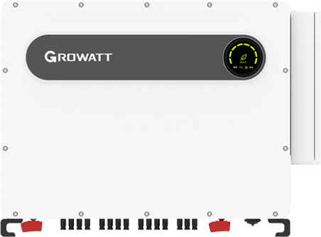
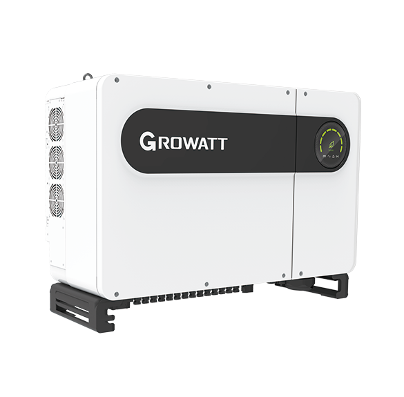
Growatt MAX 320K/333K/350K-X
Utility-scale grid-tied PV inverter
MAX 320K-X, 333K-X and 350K-X are six-MPPT, 800 V AC utility inverters. The manual defines RS485-1 monitoring; Growatt V1.24 supplies a MAX/1500 V best-effort register starting point. Read identity, state, AC output and frequency before extending monitoring. The datasheet and manual’s different MPPT ranges remain a separate electrical-design question.
- Modbus RTU
Utility-scale grid-tied PV inverter
Compatibility
Documented MAX monitoring starting map
Growatt’s manufacturer-authored V1.24 protocol lists MAX/TL3-X and MAX 1500 V families, with common serial identity and first-group state, AC power and frequency registers. It does not enumerate every newer suffix. Use it as a best-effort starting revision: compare the returned serial and live values with the nameplate and local display once before expanding the point set.
Identify the exact 320K-X, 333K-X or 350K-X nameplate, country approval, 800 V AC/transformer design, firmware, ShineMaster or PLC hardware and grid-point meter. Keep power factor, active-power limits, DRM and utility dispatch with the commissioned controller and grid operator.
Connect it with
-
Modbus Interface ZMB-3XFrom €399 ex VAT Configure Modbus Interface
-
Gateway ZGW-20From €899 ex VAT Configure Gateway
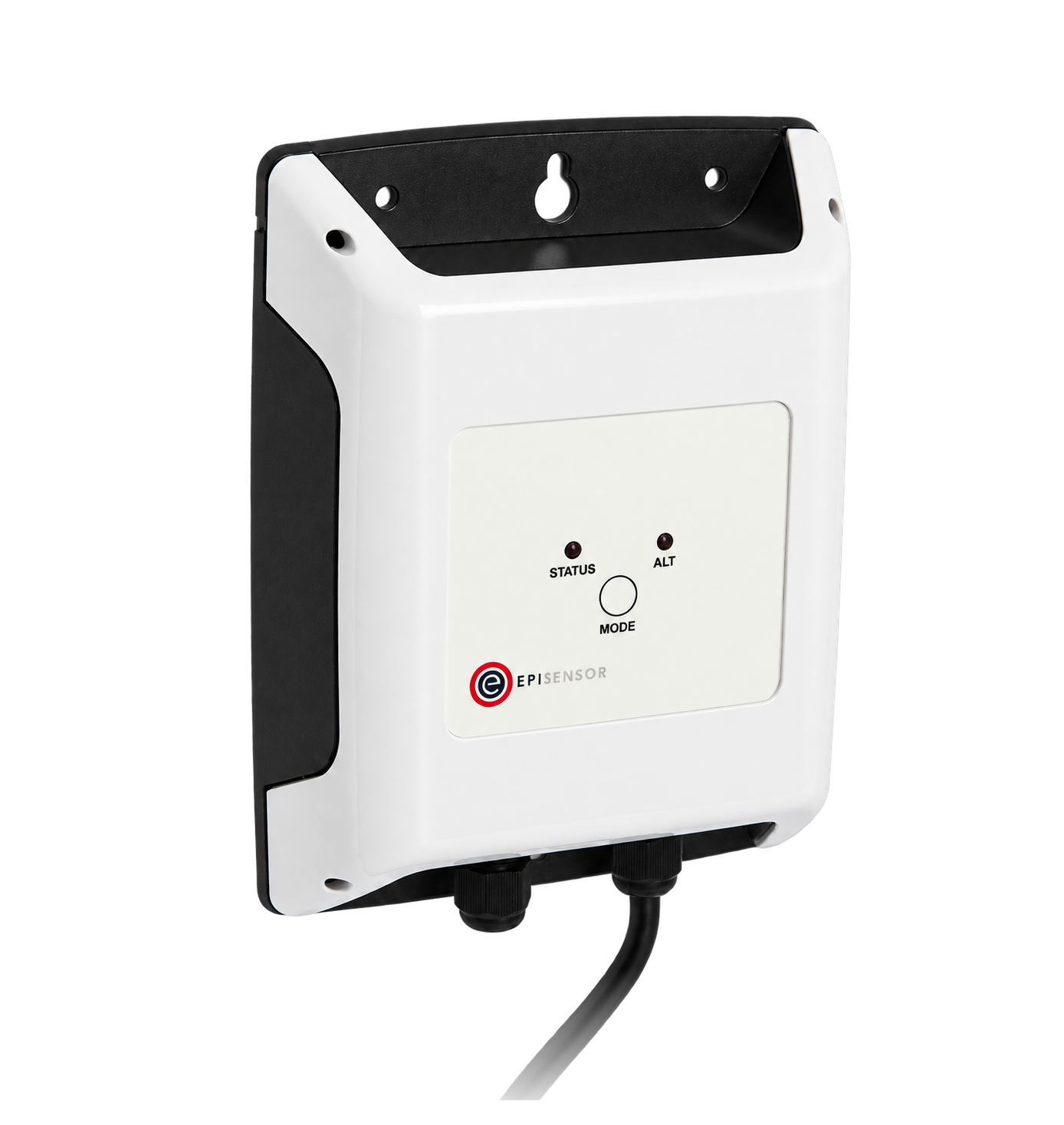
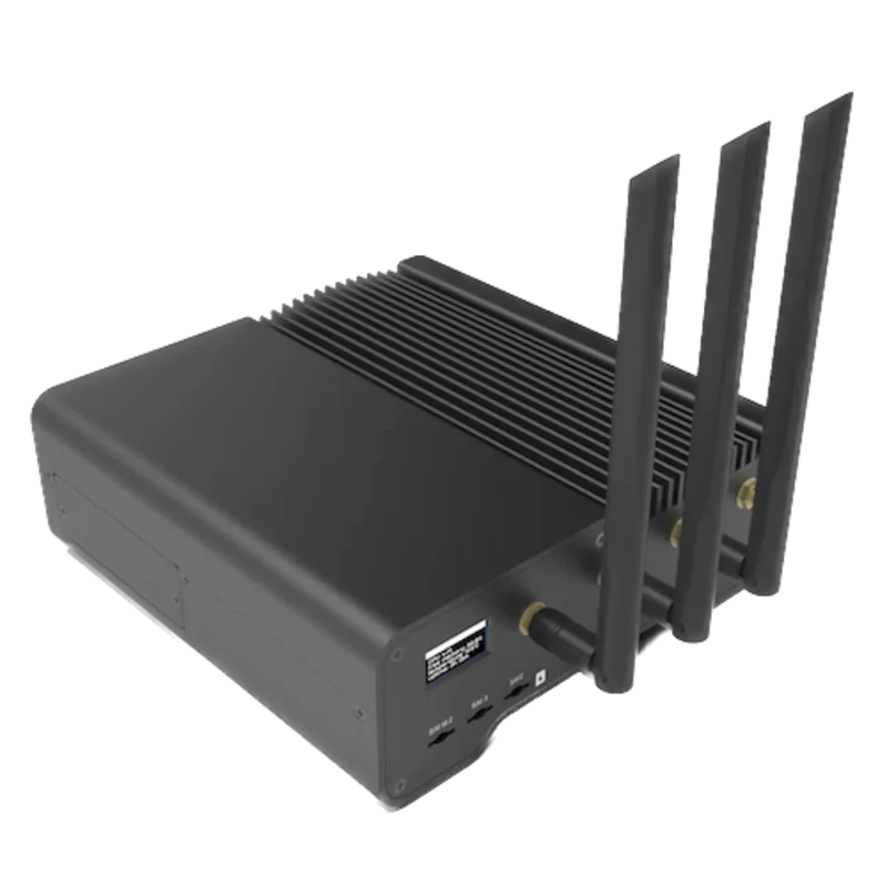
An available MAX monitoring bus returns the documented identity and first-group register layout
- Wired
- Edge
- Platforms
Models
| Models | Interface | Route into Edge |
|---|---|---|
| MAX 320K-X | 320 kW nominal AC, 480 kW recommended PV, six MPPTs and 800 V AC | Confirm nameplate and transformer/IT grid design before selecting an inverter communications path. |
| MAX 333K-X | 333 kW nominal AC, 499.5 kW recommended PV, six MPPTs and 800 V AC | Use its exact current and thermal limits; do not substitute the 320K-X schedule. |
| MAX 350K-X | 352 kW nominal AC in the model table despite the 350K marketing code; 528 kW recommended PV and 800 V AC | Record the published 352 kW rating and local approval instead of interpreting the model code as an exact 350 kW limit. |
| MAX 300K-X, MAX 100–150KTL3-X2 and other MAX LV/HV families | Different rating, AC voltage, platform or communications scope | Excluded; this guide's 800 V design and COM-terminal assumptions must not be transferred to those families. |
Specifications
The September 2026 source sheet lists 320K-X, 333K-X and 350K-X at nominal 320, 333 and 352 kW AC respectively, with 800 V AC, six MPPTs, five strings per MPPT, 80 A maximum input current per tracker, IP66 and optional GPRS/4G/Wi-Fi communications.2
- Nominal AC power
- 320, 333 and 352 kW respectively; 800 V AC, 3W+PE2
- PV tracking
- Six MPPTs, five strings each, 80 A maximum input per tracker2
- MPPT range discrepancy
- September sheet: 500–1500 V; June manual: 800–1330 V. Confirm applicable hardware revision before design23
- RS485-1 network
- COM pins 3/4 A1/B1 input and 5/6 A1/B1 output; terminal resistor option on 15/163
- RS485-2
- COM pins 7/8 listed; external meter or third-party role not defined in retained manual3
- Optional monitoring
- PLC, Wi-Fi and 4G; exact hardware and external access require site verification13
- Enclosure
- IP66, smart air cooling, 139 kg; altitude derating above 4000 m2
Interface
Documented measurements and integration boundaries for MAX 320K/333K/350K-X.
- The June 2026 manual assigns the COM port's RS485-1 input to pins 3/4 (A1/B1) and output to 5/6 (A1/B1). It says single-inverter communication can use 3/4 and a multi-inverter run can use both sets. Pins 15/16 enable matching resistance on the last inverter. Check the actual connector type, as Growatt says two appearance variants ship.
- The manual describes up to 32 inverters, 500 m and 38400 baud on its RS485 COM network. This is an inverter-bus design limit, not proof of a third-party polling capacity. Its ShineMaster diagram connects the logger to RS485-1 and uploads plant data to Growatt's server.
- RS485-2 pins 7/8 are shown in the COM table, but the retained manual does not state that they are a grid meter, northbound Edge interface or safe second-master port. Growatt also says its monitoring smart meter and environmental monitor must be designated models. Trace the actual site topology and obtain the model-specific function document.
- Optional PLC, Wi-Fi and 4G are alternative monitoring equipment choices. The V1.24 procedure below reads the inverter over RS485-1; it does not assume a PLC or USB accessory exposes Modbus TCP.
- The September 2026 datasheet gives a 500–1500 V MPPT range, while the June manual lists 800–1330 V. Both list 1500 V maximum DC input, which is a separate absolute limit. Engineering selection needs Growatt's revision-specific clarification and the installed nameplate; neither range should be silently selected.
- This is an 800 V three-wire plus PE, transformerless inverter for an IT-connected grid arrangement in the manual. The transformer, medium-voltage connection, grid-point revenue meter and plant controller must be assessed separately before claiming site export or dispatch capacity.
Assessment
MAX 320K-X, 333K-X and 350K-X RS485-1, V1.24 MAX/1500 V best-effort first group; separate 800 V electrical design and unresolved MPPT range.
- InteroperabilitySupported with conditions
- The manual defines RS485 monitoring wiring and V1.24 documents MAX first-group registers. Compare serial identity and live output locally before extending the starting set.34
- AccuracyLimited
- V1.24 defines inverter AC generation and frequency with integer types and units. Separate site metering is needed for net import/export; installed accuracy has not been measured.34
- SecurityNot yet assessed
- Third-party read-only access and logger network policy are not specified in the retained sources.3
- ReliabilityNot yet assessed
- Northbound polling, retry and stale-data behaviour need logger-specific evidence.3
- RuggednessSupported with conditions
- The later sheet lists IP66 and -30 to +60 °C, with altitude derating above 4000 m and installation restrictions in the manual.23
- ScalabilityLimited
- Growatt documents a 32-inverter, 500 m, 38400-baud RS485 arrangement; this is not an Edge fleet limit.3
Setup
Read MAX serial, AC output and frequency
Best-effort starting read from Growatt V1.24’s MAX/TL3-X and MAX 1500 V families. Use an individual slave address (1–254), configured serial framing and standard RTU CRC16. Register numbers are literal zero-based PDU offsets, not 40001-style references.
- Identity and state
- FC03 holding 23, quantity 5: PDU 03 00 17 00 05. Ten serial characters are stored two ASCII characters per word. Compare with the nameplate. FC04 input 0, quantity 1: 04 00 00 00 01; status 0 waiting, 1 normal, 3 fault in this map.
- AC output power
- FC04 input 35, quantity 3: PDU 04 00 23 00 03. Registers 35/36 are the high/low words of AC output power, unsigned, at 0.1 W per count; 37 is frequency at 0.01 Hz. Join power high word first and multiply by 0.1. Synthetic 00 01 E2 40 gives 123456 × 0.1 = 12345.6 W, not Float 32.
- Frequency and bank selection
- Synthetic frequency 13 88 is 5000 × 0.01 = 50.00 Hz. First-group input 35/36 is AC output power; 11/12 is PV3 voltage/current. MAX 1500 V adds inputs 875–999 for further channels; those additions do not change this first-group read. MIN/TL-X and MOD TL3-XH use different banks.
- Response and measurement boundary
- The PDUs omit slave address and CRC. If identity fails, check address, framing, polarity and bus ownership first. Keep exceptions, incomplete responses and timeouts unavailable, not zero. AC inverter output is not grid-point import/export; leave meter, DRM, export-limit and grid-protection control with their commissioned owner.
Acceptance: Compare the serial with the nameplate, then status, power and frequency with the local inverter display or existing Growatt monitoring. Record installed firmware alongside the V1.24 starting revision. This provides a documented starting procedure; physical Edge polling has not been tested.
-
Identify the utility-voltage inverter
Record the exact 320K-X, 333K-X or 350K-X nameplate, firmware, country approval and 800 V AC switchgear/transformer arrangement. Do not reuse a 400 V MAX family design.
-
Resolve the DC design discrepancy
Ask Growatt which MPPT operating range applies to the installed hardware and firmware. The later sheet states 500–1500 V and the manual states 800–1330 V, while 1500 V maximum input is a separate limit.
-
Trace the monitoring owner
Identify ShineMaster, optional PLC, Wi-Fi or 4G equipment, existing RS485 addresses and COM termination. Keep Growatt's designated meter and environmental equipment distinct from the inverter's own telemetry.
-
Read identity, state and AC output
Use the configured slave address and framing; the manual’s monitoring example runs at 38400 baud. Read FC03 holding 23–27 for the serial, then FC04 input 0 for state and 35–37 for AC power/frequency. Exact PDUs and integer decoding appear below. Compare with the local display; check polarity, addressing and bus ownership first if the serial fails.
-
Qualify site flexibility separately
Use a trusted grid-point meter and approved controller to establish net import/export, transformer limits, curtailment rights, reactive duty and fail-safe behaviour. Do not send inverter writes from this selection guide.
Common questions
- Is MAX 350K-X exactly a 350 kW nameplate?
- The September 2026 model table calls it MAX 350K-X but lists 352,000 W nominal AC power. Confirm the site-specific approval and thermal schedule rather than interpreting the marketing code as the exact rating.2
- Which MPPT operating range is correct?
- The current September sheet says 500–1500 V; the linked June manual says 800–1330 V. Both cite 1500 V maximum input. Treat the operating range as unresolved until Growatt identifies the applicable hardware and firmware revision.23
- Is RS485-2 the grid meter or an Edge port?
- The manual lists RS485-2 pins 7/8 but does not assign either a grid-meter or third-party Edge role to them. Growatt's designated meter requirement and installed site wiring must be checked before making that claim.3
- Does optional PLC mean direct HPLC or Modbus TCP integration?
- No direct endpoint is established in these documents. The product page advertises optional PLC and the manual lists monitoring via RS485, PLC, Wi-Fi or 4G. Identify the actual Growatt module, logger and its authorised external interface before choosing a protocol.13
Related devices
Sources
- MAX 320–350K-X utility inverter product page (opens in a new tab)
- MAX 320–350K-X datasheet, September 2026 (opens in a new tab) (PDF)
- MAX 300–350K-X User Manual, June 2026 link (opens in a new tab) (PDF)
- Growatt Inverter Modbus RTU Protocol V1.24 (public mirror) (opens in a new tab)
Further reading
Product names and trademarks belong to their owners. Publication does not imply endorsement or a commercial relationship.