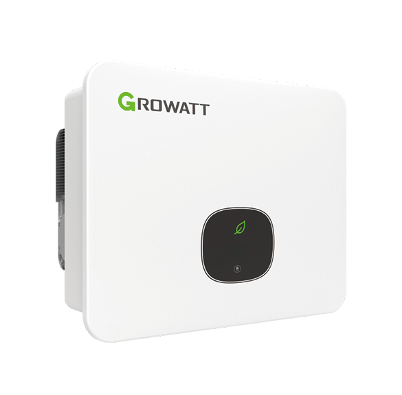
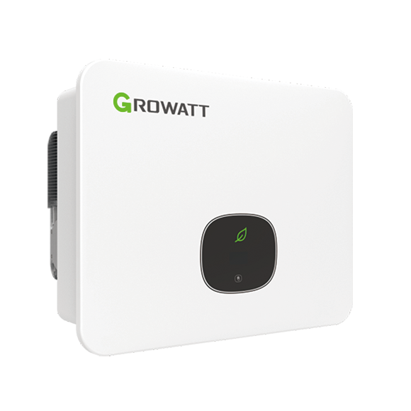
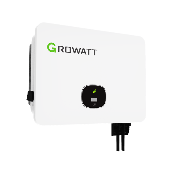
Growatt MID 15–30KTL3-X / X2
Commercial PV inverter
Growatt groups MID 15–25KTL3-X and MID 17–30KTL3-X2 on one product page, with separate manuals, terminal layouts and two-MPPT ratings. Its public V1.24 protocol lists MID under the TL3-X register layout. Use the bounded identity and output-power read below as a best-effort starting point, preserving the X/X2 wiring and the distinct 30KTL3-X2-1 model.
- Modbus RTU
Commercial PV inverter
Compatibility
Documented TL3-X monitoring starting map
Growatt’s manufacturer-authored V1.24 map lists MID in the TL3-X family and supplies serial identity, inverter status, AC output power and frequency. The map does not enumerate every newer suffix: confirm the nameplate, returned serial and decoded values against the local display before extending this starting set.
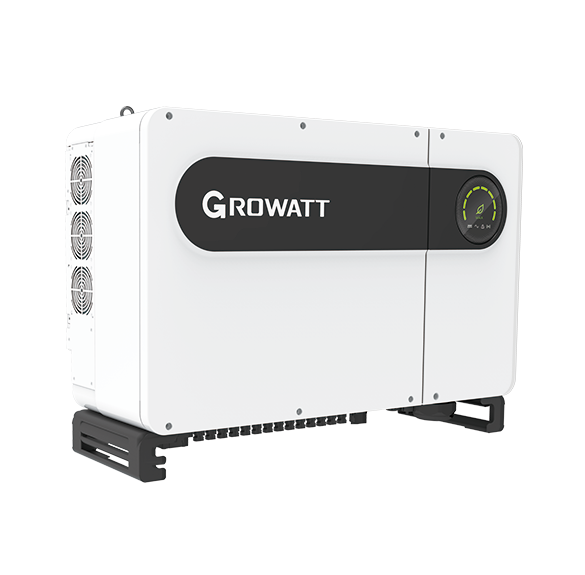
MID 15/17/20/22/25KTL3-X or MID 17/20/25/30KTL3-X2 in the two May 2026 Growatt datasheets. The two-MPPT MID 30KTL3-X2 here is not the three-MPPT MID 30KTL3-X2-1 from the separate 30–50 kW family. Excludes MID XH, X3, XL2 and other regional variants.
Connect it with
-
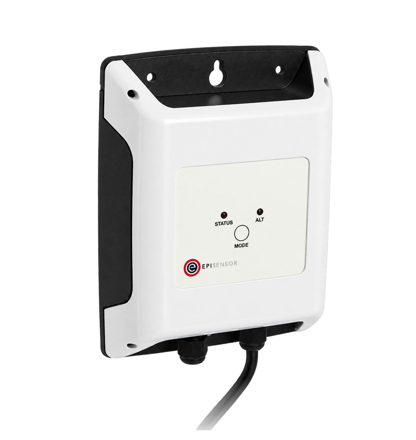
Modbus Interface ZMB-3XFrom €399 ex VAT Configure Modbus Interface
-
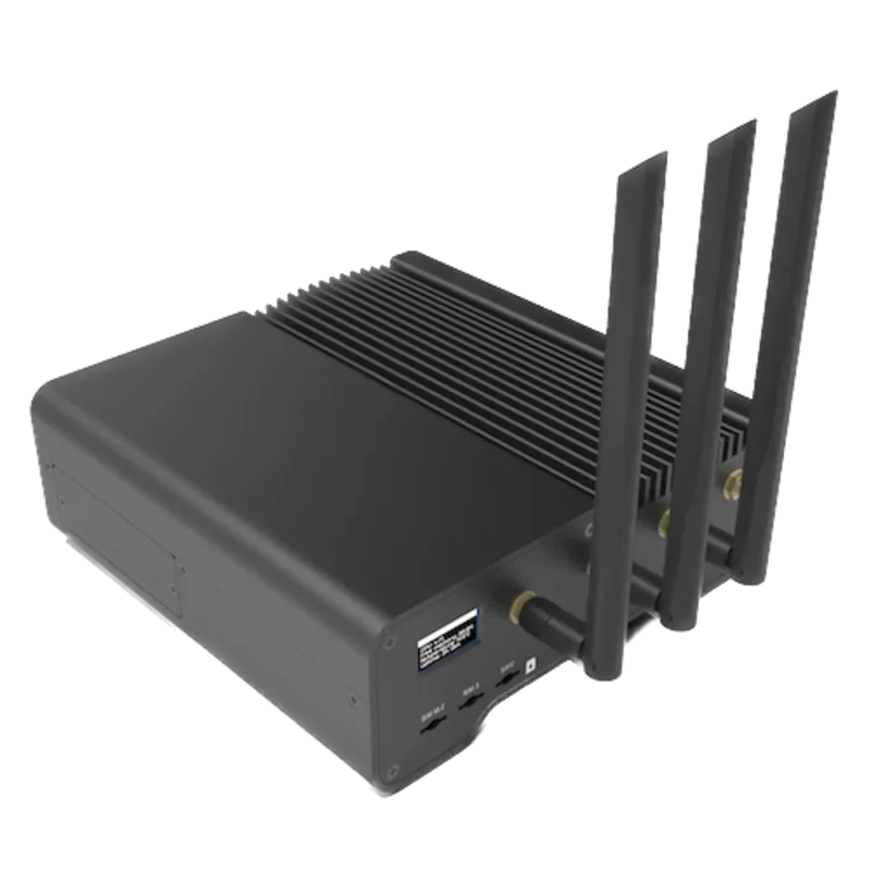
Gateway ZGW-20From €899 ex VAT Configure Gateway
The installed MID X or X2 has an available monitoring connection and responds with the documented TL3-X layout
- Wired
- Edge
- Platforms
Models
| Models | Interface | Route into Edge |
|---|---|---|
| MID 15/17/20/22/25KTL3-X | Two MPPTs; the May 2026 X datasheet gives IP65 and 27 A per MPPT on 15–22 kW | Use the X manual. Its six-pin RS485 block assigns monitoring to pins 3/4 and anti-backflow meter to pins 5/6. |
| MID 17/20/25/30KTL3-X2 | Two MPPTs; the X2 datasheet gives IP66 and rating-dependent strings and input currents | Use the X2 manual. Its 16-pin block assigns monitoring A1/B1 to pins 3/4 and meter A3/B3 to pins 7/8; pins 5/6 are marked reserved BAT communication. |
| MID 30KTL3-X2 versus MID 30KTL3-X2-1 | Two-MPPT 30KTL3-X2 versus three-MPPT 30KTL3-X2-1 in the separate larger-family sheet | Do not drop the -1 suffix or reuse the other family's electrical and interface assumptions. |
Specifications
Growatt's May 2026 English sheets place five MID X variants at 15–25 kW and four MID X2 variants at 17–30 kW. Both groups have two MPPTs, but string allocation and input-current limits vary by exact rating. The X sheet gives IP65; the X2 sheet gives IP66.23
- MID X variants
- 15, 17, 20, 22 and 25 kW; two MPPTs; IP652
- MID X2 variants
- 17, 20, 25 and 30 kW; two MPPTs; IP663
- 30 kW X2 PV input
- Two MPPTs, with two and three strings respectively3
- X monitoring and meter
- Monitoring pins 3/4, meter pins 5/6 in the X manual's six-pin RS485 block4
- X2 monitoring and meter
- Monitoring pins 3/4, meter pins 7/8, reserved BAT pins 5/6 in the X2 manual's 16-pin block5
Interface
Documented measurements and integration boundaries for MID 15–30KTL3-X / X2.
- The X manual's monitoring and meter pin groups differ from the X2 manual's groups. Check the installed model and terminal diagram before connecting any cable.
- A Growatt Shine USB logger, SEM controller and RS485 monitoring bus are different paths. Identify the actual source and ownership of every proposed value.
- The first read uses inverter AC generation and grid frequency; it does not replace independent point-of-connection import/export metering. No Edge import template or control command is provided.
Assessment
Two-MPPT MID 15–25KTL3-X and MID 17–30KTL3-X2 only. Use each model's own terminal drawing and installed firmware with the V1.24 starting read below; physical Edge polling has not been tested and no control command is provided.
- InteroperabilitySupported with conditions
- The exact manuals define monitoring terminals; V1.24 explicitly lists MID/TL3-X registers. Serial identity and local-value comparison qualify the starting set on the installed unit.458
- AccuracyNot yet assessed
- The map defines unsigned words, AC power scaling and frequency. Installed accuracy and physical polling behavior have not been measured.458
- SecurityNot yet assessed
- The retained sources do not establish third-party authentication, encryption or read-only separation.45
- ReliabilityLimited
- Electrical limits are documented, while third-party coexistence, stale data and recovery remain site-test questions.235
- RuggednessSupported with conditions
- The separate datasheets publish IP65 for X and IP66 for X2 with operating limits, subject to installation conditions.23
Setup
Read MID serial, AC output and frequency
Best-effort TL3-X layout from Growatt V1.24. Use an individually addressed inverter (1–254), the configured serial framing and standard RTU CRC16. Register numbers below are literal PDU offsets, not 40001-style references.
- Identity and state
- FC03 holding 23, quantity 5: PDU 03 00 17 00 05. Ten serial characters are stored two ASCII characters per word. Compare with the nameplate. FC04 input 0, quantity 1: 04 00 00 00 01; status 0 waiting, 1 normal, 3 fault in this map.
- AC output power
- FC04 input 35, quantity 3: PDU 04 00 23 00 03. Registers 35/36 are the high/low words of AC output power, unsigned, at 0.1 W per count; 37 is frequency at 0.01 Hz. Join power high word first and multiply by 0.1. Synthetic 00 01 E2 40 gives 123456 × 0.1 = 12345.6 W, not Float 32.
- Frequency and bank selection
- Synthetic frequency 13 88 is 5000 × 0.01 = 50.00 Hz. This TL3-X table places AC power at 35/36; 11/12 are PV3 voltage/current, not AC power. MIN/TL-X and MOD TL3-XH use other register banks. Compare values with the inverter display rather than silently changing banks.
- Response and measurement boundary
- The PDUs omit slave address and CRC. If identity fails, check address, framing, polarity and bus ownership first. Keep exceptions, incomplete responses and timeouts unavailable, not zero. AC inverter output is not grid-point import/export; leave meter, DRM, export-limit and grid-protection control with their commissioned owner.
Acceptance: A concrete source-backed first read for the documented MID/TL3-X layout. Physical Edge polling has not been tested. Record installed firmware once and compare the small starting set; a newer suffix may extend the map without invalidating this approach.
-
Read the complete nameplate
Record X or X2, all digits and suffixes, country grid configuration, serial number and firmware. Verify whether a 30 kW nameplate says 30KTL3-X2 or 30KTL3-X2-1.
-
Use the matching terminal drawing
The X manual uses a six-pin RS485 block with a 5/6 meter pair. The X2 manual uses a 16-pin block with a 7/8 meter pair and reserved 5/6 BAT pins. Photograph the installed connector before planning an interface.
-
Trace logger and meter ownership
Map Shine or SEM accessories, the USB logger, any inverter chain, CT or export meter and the point-of-connection meter. Do not treat a meter bus as a spare monitoring port.
-
Start with identity, status and output power
Use the configured slave address and serial settings. Read holding23–27 for the ten-character serial; compare it with the nameplate. On the TL3-X layout, read input0 status and input35–37 for AC power and frequency. The worked check gives exact PDUs and scaling; compare fresh values with the local display.
-
Keep control in its engineered system
Export limits, ripple/DRM inputs and reactive-power settings need separate plant-control and protection review. This guide publishes no Edge write path.
Common questions
- Are MID 30KTL3-X2 and MID 30KTL3-X2-1 interchangeable?
- No. Growatt's two-MPPT 17–30 kW X2 sheet names MID 30KTL3-X2. The separate 30–50 kW X2 family documents MID 30KTL3-X2-1 with three MPPTs. Preserve the suffix when selecting documents and configuring a site.37
- Can one terminal pinout be used for both X and X2?
- No. Their manuals use different connector layouts. The X manual assigns the meter to pins 5/6; the X2 manual assigns it to pins 7/8 and marks 5/6 as reserved battery communication.45
- Does RS485 or a Shine logger prove an Edge integration?
- The manuals establish the monitoring wiring and V1.24 supplies a MID/TL3-X starting map. Follow the identity and power check below on an available bus. A Shine USB logger remains a separate route; do not assume it exposes TCP or allows a second serial master.458
Related devices
Sources
- MID 15-30KTL3-X/X2 product page (opens in a new tab)
- MID 15-25KTL3-X English datasheet, May 2026 update (opens in a new tab) (PDF)
- MID 17-30KTL3-X2 English datasheet, May 2026 update (opens in a new tab) (PDF)
- MID 10-25KTL3-X user manual, May 2023 (opens in a new tab) (PDF)
- MID 20-30KTL3-X2 user manual, November 2024 (opens in a new tab) (PDF)
- MID 20-30KTL3-X2 product page and exact X2 image (opens in a new tab)
- MID 30-50KTL3-X2 regional datasheet distinguishing the -1 model (opens in a new tab) (PDF)
- Growatt Inverter Modbus RTU Protocol V1.24 (public mirror) (opens in a new tab)
Further reading
Product names and trademarks belong to their owners. Publication does not imply endorsement or a commercial relationship.