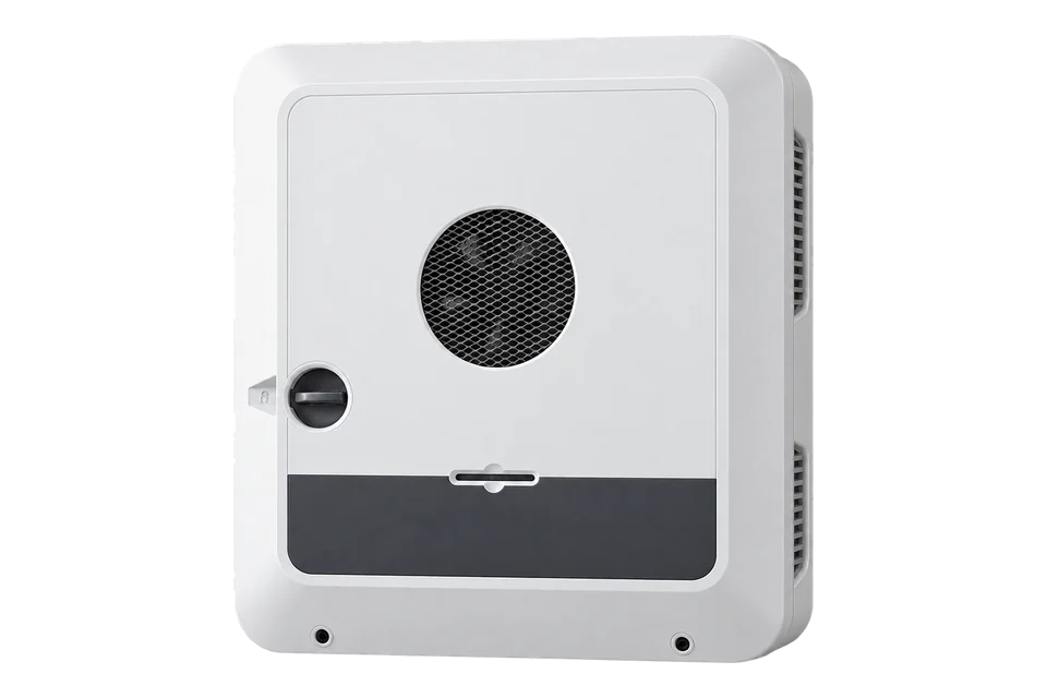
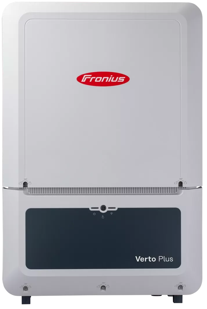
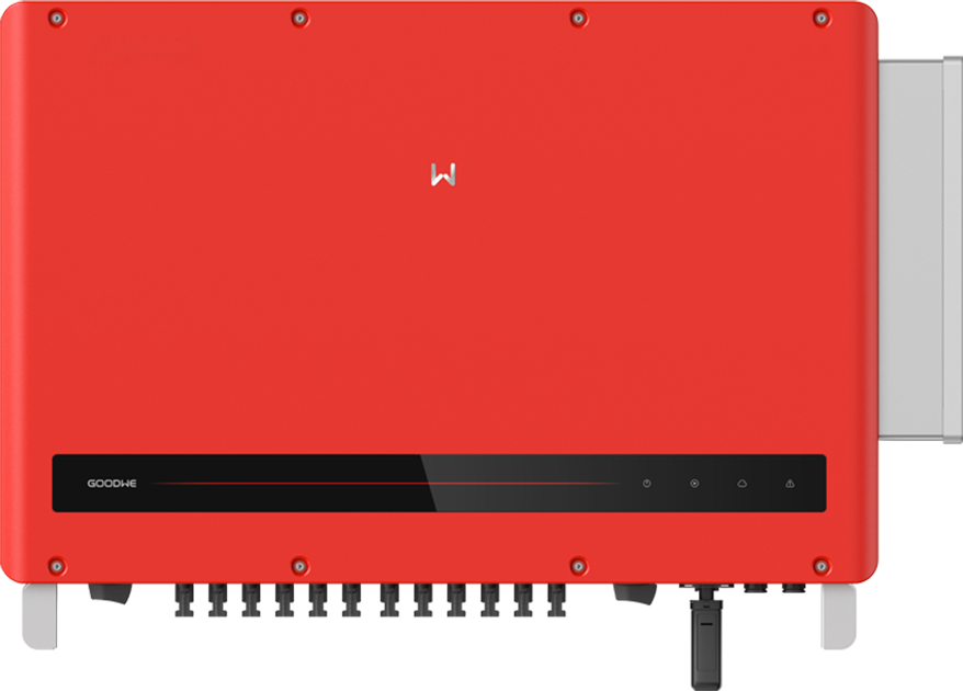
Fronius Symo GEN24 Plus 6–10 kW
Three-phase hybrid solar inverter
Symo GEN24 Plus combines solar conversion and a battery connection in a three-phase inverter. Its local Modbus interface exposes SunSpec data to Edge. Inverter production, battery data and a connected site meter are different data sets: identify the right device and discover its model list before choosing measurements.
- Modbus TCP
- Modbus RTU
Three-phase hybrid solar inverter
Compatibility
Compatible through Modbus TCP or RTU
Edge reads the inverter’s local Modbus server. Fronius documents TCP and RTU transport, SunSpec identification and the model-specific measurement layout.
This guide covers the original Symo GEN24 Plus 6.0, 8.0 and 10.0 kW family. Check the nameplate and firmware; Primo, non-Plus, SC and regional variants have separate electrical specifications. This setup reads data and leaves inverter and battery control disabled.
Connect it with
-
Modbus Interface ZMB-3XFrom €399 ex VAT Configure Modbus Interface
-
Gateway ZGW-20From €899 ex VAT Configure Gateway
-
Evaluation Gateway on a Raspberry Pi Edge with one device licensedFree Set up Evaluation Gateway on a Raspberry Pi


When the inverter is connected to the site IP network
- Modbus
- Edge
- Platforms
When an available inverter interface is configured as a Modbus RTU server
- Modbus
- Edge
- Platforms
Models
| Models | Interface | Route into Edge |
|---|---|---|
| Symo GEN24 Plus 6.0 / 8.0 / 10.0 | Three-phase hybrid inverter; local SunSpec Modbus TCP or RTU | Discover the configured SunSpec models; use inverter unit ID 1 over TCP. |
| Fronius Smart Meter connected to GEN24 | Separate meter data exposed through the inverter, with its own device identity and models | Read its configured unit ID, normally 200 for the first meter, and confirm the installation location and power sign. |
| Primo GEN24 / Symo GEN24 SC / non-Plus variants | Different phase, power or hardware scope; current manuals cover several distinct variants | Verify the exact model and its model list before reusing any measurements or electrical specifications. |
Specifications
The 6, 8 and 10 kW Symo GEN24 Plus models are three-phase hybrid inverters. A battery connection and backup functions do not mean that a battery or a complete backup installation is supplied. For energy monitoring, distinguish inverter generation from the separate Smart Meter measurement at the grid connection.2
- Rated AC power
- 6.0, 8.0 or 10.0 kW, according to the exact model2
- AC connection
- Three-phase with neutral and protective earth; nominal 230/400 V or 220/380 V configurations documented2
- Local data access
- Modbus TCP over Ethernet or WLAN; Modbus RTU over RS-4851
- TCP identity
- Inverter unit ID 1; connected meters use separate IDs, first meter default 2001
- Register model
- SunSpec common identification followed by model blocks; discover block IDs and lengths instead of assuming fixed measurement addresses1
- Enclosure and climate
- IP66; -25 to +60 °C ambient; controlled forced-air cooling and manufacturer siting/clearance requirements2
Interface
Documented measurements and integration boundaries for Symo GEN24 Plus 6–10 kW.
- Manufacturer, model, serial number and software version from the SunSpec common model.
- AC current, voltage, power, frequency and energy from the inverter model that the device actually exposes.
- Scale factors for int+SF models, or floating-point values for float models; the two layouts are not interchangeable.
- Inverter operating state and event indicators alongside power values.
- Connected Smart Meter import/export and signed site power from its separate unit ID, interpreted using the configured meter location.
- Battery measurements only when the installed battery and firmware expose the relevant models; reading them does not authorise battery control.
Assessment
Original three-phase Symo GEN24 Plus 6.0, 8.0 and 10.0 kW models. Monitoring only; inverter control, battery dispatch and backup design are outside this setup.
- InteroperabilityWell supported
- Fronius publishes local TCP/RTU access, function codes, addressing and SunSpec model discovery, including a worked manufacturer read.1
- AccuracySupported with conditions
- Inverter measurements and connected meter models are documented, but they describe different electrical boundaries. Use the site meter for grid exchange; the inverter is not a substitute for a billing meter.12
- SecuritySupported with conditions
- The interface provides an explicit Allow Control setting and a control-IP restriction. Keep control disabled for monitoring and limit access to the local Modbus endpoint.1
- ReliabilitySupported with conditions
- The manufacturer publishes operating limits, cooling arrangements, diagnostics and software-update procedures. Monitoring must preserve unavailable/stale states during inverter shutdown or communications loss.12
- RuggednessWell supported
- IP66, -25 to +60 °C operation and documented indoor/outdoor mounting conditions provide a defined installation envelope. Siting and cooling clearances still apply.2
- ScalabilitySupported with conditions
- IP address plus inverter unit ID identifies each TCP device; RTU requires unique configured IDs. SunSpec discovery avoids assuming one register layout across versions.1
Setup
Read the manufacturer before any power values
Fronius provides this four-register read in its Modbus manual. It tests device identity and the unusual address convention without issuing a control command.
- Transport and target
- Modbus TCP to the configured inverter IP and port, unit ID 1; or RTU using the configured slave ID
- Function
- FC03 Read Holding Registers
- Document register
- 40005, manufacturer string Mn
- Zero-based PDU address
- 40004 decimal, 0x9C44. Do not subtract 40001 as if this were a conventional 4xxxx reference.
- Length
- 4 registers, 8 data bytes
- Request PDU
- 03 9C 44 00 04; the client supplies the TCP header or RTU address and CRC
- Manufacturer example data
- 46 72 6F 6E 69 75 73 00, ASCII Fronius followed by a NUL byte
- Decode
- Two characters per register, high byte first. This is a string, not a float or a power reading.
- Conditional power request
- For returned SunSpec model 103 only, let H be its discovered header address. FC03 at H + 14, quantity 2, reads signed int16 W and signed W_SF. If H = 40070, read wire address 40084 (0x9C94), PDU 03 9C 94 00 02. This is an example header position; models 113/203/213 use their own layouts.
- Signed scaling example
- Synthetic bytes 30 39 FF FF decode to W = 12345 and W_SF = -1: 12345 × 10^-1 = 1234.5 W. These are two signed integer registers, not Float32. Value 0x8000 means unavailable, not zero. Compare decoded power with the inverter interface.
Acceptance: The documented response identifies Fronius only. Next verify model and serial number, then discover the measurement model and compare a live reading. This is a manufacturer example and independent decoder check, not a claim that a physical inverter was tested.
-
Identify the inverter and meter roles
Record the exact nameplate, firmware and any connected battery and Smart Meter. Decide whether the required value is inverter generation or site import/export. They come from different SunSpec devices, even when both are reached at the same IP address.
-
Enable the local read interface
In the inverter web interface, open Communication, then Modbus. Enable the intended TCP server or RTU mode and record the TCP port (502 or 1502) or the actual serial settings. Leave Allow Control disabled for this monitoring setup; do not change existing export limits or battery policies.
-
Add the endpoint in Edge
For TCP, use the inverter IP address, its configured port and unit ID 1. For RTU, use the configured slave ID and an isolated serial interface on a bus with one master. First perform the manufacturer read below; a successful TCP connection alone does not identify the data source.
-
Discover the SunSpec layout
Read the identification and common model, then follow each model ID and length to find the relevant inverter block. The configured float and int+SF choices change the data layout. Retain the discovered IDs, lengths, offsets and scale factors with the setup rather than copying a fixed address from another installation.
-
Check power, sign and stale data
Compare inverter AC power with the inverter interface and site power with the connected meter at the same time. Check the meter’s configured location before interpreting positive and negative power. Confirm a failed poll stays a failed or stale reading instead of becoming zero, and repeat identity/layout checks after a firmware or model-type change.
-
Read model-103 power
When discovery returns model 103, read FC03 at its header +14, two registers, for W and W_SF. Decode both as signed 16-bit integers and calculate W × 10^W_SF in watts. Use the returned model’s own definition for another representation; the worked example below gives the wire request and a scaling check.
Common questions
- Why does register 40001 not become address 0?
- Fronius uses 40001 as the actual one-based SunSpec register number. Subtract one only: the request address is 40000. The manual explicitly warns that these numbers are not the usual Modicon 4xxxx notation.1
- Can I copy the AC power address from another GEN24?
- First check the configured SunSpec model type and discover the returned model list. Float and int+SF representations have different lengths and offsets. Use the discovered block and its point definition; a plausible value at a copied address is not sufficient proof.1
- Does inverter power show the building’s grid import?
- No. Inverter output describes the inverter. A Smart Meter at the grid connection measures site exchange and is exposed as a separate device. Its configured location determines the meaning of the signed power value.1
- Do I need to enable Allow Control to monitor the inverter?
- Keep Allow Control disabled for this read-only setup. That option enables functions such as on/off, power reduction, reactive-power settings and battery control; those are a separate control-system design.1
Related devices
Sources
- GEN24 Modbus TCP and RTU operating instructions (opens in a new tab)
- Symo GEN24 6–10 kW Plus and 6–12 kW Plus SC operating instructions (opens in a new tab)
- SunSpec three-phase inverter model 103 definition (opens in a new tab)
Further reading
Product names and trademarks belong to their owners. Publication does not imply endorsement or a commercial relationship.