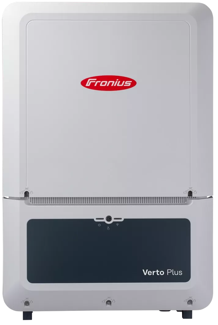
Fronius Verto Plus 15–33.3
Commercial hybrid PV inverter
Six hybrid inverters from 15.0 to 33.3 kW share a local SunSpec Modbus TCP server for production monitoring. RS-485 meter channels and the battery link have different roles. Backup and dispatch need a commissioned control design.
- Modbus TCP
- Modbus RTU
Commercial hybrid PV inverter
Compatibility
Local SunSpec Modbus TCP monitoring
The July 2026 Verto Plus datasheet specifies Modbus TCP SunSpec on Ethernet, and the exact-family operating instructions define TCP Server, ports 502 or 1502, SunSpec float or integer/scale-factor models and the distinct Allow Control switch. A read-only Edge client can be qualified against the installed server and discovered model list.
Verto Plus 15.0, 17.5, 20.0, 25.0, 30.0 and 33.3 only, using installed firmware and country settings. Configure the inverter's TCP Server on a restricted site LAN; keep Allow Control off for read-only monitoring. Meter roles, RS-485 channel allocation, battery Modbus O and backup switchgear are separate. Do not use this guide to authorize writes or grid services.
Connect it with
-
Modbus Interface ZMB-3XFrom €399 ex VAT Configure Modbus Interface
-
Gateway ZGW-20From €899 ex VAT Configure Gateway


The commissioned Plus inverter has TCP Server enabled and an approved site LAN route
- Modbus
- Edge
- Platforms
Models
| Models | Interface | Route into Edge |
|---|---|---|
| Verto Plus 15.0 / 17.5 / 20.0 | 15, 17.5 or 20 kW rated AC; three MPPTs with two strings each; 28 A usable input and 50 A short-circuit limit per MPPT. Datasheet peak backup output is 30 kVA for up to 10 seconds with sufficient PV and battery power. | Use the Plus TCP server and discovered SunSpec models; check the installed rating and battery before interpreting power or backup status. |
| Verto Plus 25.0 / 30.0 / 33.3 | 25, 29.99 or 33.3 kW rated AC in the July 2026 datasheet; the 30.0 label is a power class, not a 30,000 W guaranteed rating. Three MPPTs; peak backup output is 50 kVA for up to 10 seconds under stated conditions. | Check the exact nameplate and country setup, then discover the TCP SunSpec profile. Do not reuse limits from the non-Plus Verto 30.0. |
Specifications
The six Plus variants span 15.0 to 33.3 kW, with three MPPTs and two PV strings per tracker, 150–870 V usable MPP range and 1000 V maximum DC input. The July 2026 datasheet specifies a 150–700 V battery input, IP66 enclosure, 865 × 574 × 279 mm and 43 kg. The country-specific nameplate remains authoritative for grid connection and backup design.123
- PV input
- Three MPPTs, two strings each; 28 A usable / 50 A short-circuit per MPPT; 150–870 V MPP; 1000 V maximum DC2
- Rated AC power
- 15, 17.5, 20, 25, 29.99 and 33.3 kW respectively in the July 2026 sheet2
- Battery side
- One 150–700 V input; approved Fronius Reserva/Reserva Pro and listed BYD Battery-Box variants, subject to datasheet exclusions12
- Local TCP
- RJ45 LAN 10/100 Mbit; SunSpec TCP server on configured port 502 or 1502; float or int + SF model type12
- RS-485
- Two two-wire Modbus RTU SunSpec channels, also used for Fronius Smart Meter and system components12
- Battery communications
- Separate Modbus O / RJ45 / 12 V battery connection on Plus devices1
- Full Backup
- Battery and external grid switching required; about 11 s switchover; temporary 30 kVA or 50 kVA boost by class under datasheet conditions123
- Enclosure
- IP66; 865 × 574 × 279 mm; 43 kg; active cooling2
Interface
Documented measurements and integration boundaries for Verto Plus 15–33.3.
- Ethernet is an RJ45 10/100 Mbit connection; the datasheet names Modbus TCP SunSpec and JSON. The manual offers TCP ports 502 or 1502 and float or int + SF SunSpec inverter model choices. Site settings and the discovered model list determine the actual reader configuration.
- Modbus 0 and Modbus 1 are two separate two-wire RS-485 channels. The manual's RTU Server setting selects M0 or M1, address, baud rate and parity; Fronius meters and other system components may already occupy those channels. Do not treat a meter configuration as a free Edge bus.
- The Plus battery connection is a separate Modbus O/RJ45/12 V interface for approved storage. Its RJ45 connector does not make it an Ethernet or Edge input. Battery charge limits depend on the paired battery and installed firmware.
- The manual states that Modbus TCP/IP is unsecured. Restrict its network reach and do not forward the server port to the Internet. Allow Control enables on/off, power reduction, reactive settings and battery control; read-only monitoring leaves it off.
- Full Backup requires a battery and external grid switching equipment. Datasheet switching time is approximately 11 seconds, so it is not an uninterruptible power supply. Peak boost figures last at most 10 seconds with sufficient PV and battery power.
- A Fronius primary meter at the feed-in point supplies site export and import context. Inverter production alone cannot prove net export or a flexibility dispatch outcome. Multiple Inverter Control and its priorities are a separate, commissioned Fronius plant function.
Assessment
Six Verto Plus 15.0–33.3 variants using the commissioned local SunSpec TCP server; meter, battery, backup and dispatch functions separate.
- InteroperabilitySupported with conditions
- The exact-family manual and sheet document a local SunSpec TCP server, two selectable ports and model representations; commissioned settings and model discovery remain necessary.12
- AccuracySupported with conditions
- SunSpec inverter readings support production monitoring; feed-in-point import and export need a separate meter and acceptance check.12
- SecurityLimited
- Fronius calls Modbus TCP/IP unsecured. Restrict the LAN and keep Allow Control disabled for a reader.1
- ReliabilityNot yet assessed
- The retained documents do not establish site availability, stale-data thresholds or backfill to Edge.1
- RuggednessSupported with conditions
- The datasheet specifies IP66, active cooling and an indoor/outdoor mounting range; maintain the specified clearances and installation orientation.2
- ScalabilityLimited
- Each commissioned TCP endpoint needs its own discovered model set. Fronius Multiple Inverter Control has separate client/priority rules that an added reader must not disrupt.1
Setup
-
Record the exact Plus installation
Identify one of the six Plus nameplates, installed firmware, country setting, meter position, battery pairing, grid switchgear and any existing Fronius plant controller. Keep the non-Plus Verto 30.0 manual separate.
-
Prepare a restricted LAN
Connect the inverter's LAN port to the approved site network. Use an address reachable only from authorized local systems; do not publish the unsecured Modbus service to the Internet.
-
Enable the read path
In Communication > Modbus, confirm TCP Server, the configured port 502 or 1502 and the chosen SunSpec float or int + SF model type. Leave Allow Control off. Record any existing client or Multiple Inverter Control dependency before changing settings.
-
Discover and compare readings
From Edge, discover the actual SunSpec model set. Compare time-aligned AC power, cumulative production and operating state with the Fronius interface. Resolve scale factors, stale data and shutdown behavior on site; do not assume that inverter power equals grid export.
-
Design control separately
Any VPP or export-control project needs the utility-approved control matrix, technician access, meter location, priority and fail-safe plan, accepted command map, and battery/backup coordination. This guide authorizes no writes.
Common questions
- Can Edge monitor a Verto Plus locally without Fronius Solar.web?
- Yes, for a commissioned local read-only path. Fronius documents a SunSpec Modbus TCP server on the inverter's Ethernet connection. Enable the server on the approved LAN, select its configured port and model type, and validate the discovered values; cloud registration is a separate function.12
- Is the battery RJ45 port an Ethernet port for Edge?
- No. Fronius labels that separate Plus-only connector Modbus O, RJ45 and 12 V battery power. Use the LAN port for the documented TCP server, and leave battery wiring to the approved storage design.12
- Does the two-port RS-485 specification mean a free third-party bus?
- No. Modbus 0 and Modbus 1 can be assigned to Fronius meters or system components, and the manual describes distinct RTU Server settings. Check installed terminal ownership before any added device; the read path in this guide uses TCP.12
- Can a Verto Plus provide uninterrupted backup or VPP dispatch from this guide?
- Full Backup needs a battery and external grid switch, with about 11 seconds of transfer in the datasheet. The local Modbus menu offers an Allow Control switch, but writing commands requires a separately approved site control and fail-safe design. No dispatch or UPS behavior is implied by read-only monitoring.123
Related devices
Sources
- Fronius Verto Plus 15–33.3 kW operating instructions (opens in a new tab)
- Fronius Verto Plus datasheet EN V07 July 2026 (opens in a new tab) (PDF)
- Fronius Verto and Verto Plus product page (opens in a new tab)
Further reading
Product names and trademarks belong to their owners. Publication does not imply endorsement or a commercial relationship.