Gossen Metrawatt ENERGYMID EM2289/EM2389
Three-phase energy meter
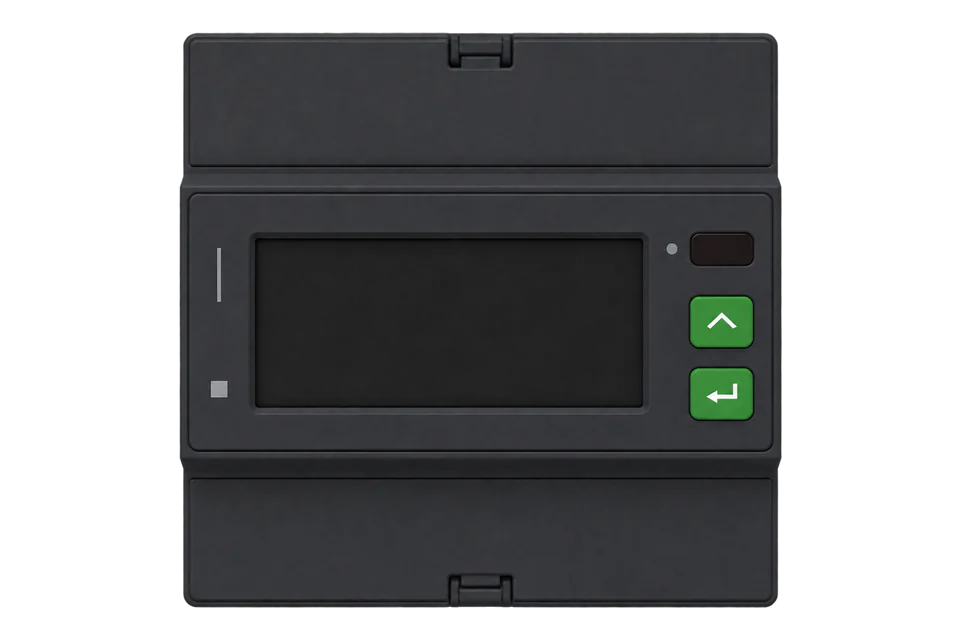
ENERGYMID is Gossen Metrawatt's family of MID-approved, four-module DIN-rail energy meters. With feature W7 the meter has an RS-485 port with Modbus RTU, and Gossen Metrawatt's interface description 3-349-910-03 covers all U228x-W7 and U238x-W7 meters: the EM2281 and EM2289 for direct connection at 5(80) A and the EM2381, EM2387 and EM2389 through 1(6) A transformers. Addresses are zero-based and sent as printed. Voltage, current and power are a 16-bit mantissa with a shared exponent register; energy is a 32-bit mantissa in Wh multiplied by a primary energy factor. The multifunctional M1 and M3 variants add voltage, current, power and frequency to the energy counters.
Compatibility
Compatible with EpiSensor Edge over Modbus RTU
ENERGYMID meters with feature W7 are compatible with EpiSensor Edge over Modbus RTU on their RS-485 bus terminals, read through a ZMB-31 Modbus Interface or a Gateway serial port. Gossen Metrawatt publishes interface description 3-349-910-03 with zero-based addresses, function codes, format types and units.
EM2281, EM2289, EM2381, EM2387 and EM2389 with feature W7 (Modbus RTU), read with interface description 3-349-910-03. The TCP/IP (W4), M-Bus (W2), LON (W1) and LPWAN (W8) variants have their own interface descriptions and are outside this guide. Site check: read frequency at register 11 and compare it with the display. Read-only monitoring: no writes to the parameter registers from 10000.
Connect it with


For a meter in a distribution board where a wireless link avoids running a data cable back to the Gateway
- Modbus
- Wireless
- Edge
- Platforms
When a row of meters shares one wired RS-485 bus near the Gateway
- Modbus
- Edge
- Platforms
Models
| Models | Interface | Route into Edge |
|---|---|---|
| EM2289 (U2289) with W7: U2289-V018 (standard M0) and U2289-V028 (multifunctional M1) | 4-wire, direct connection 5(80) A, 400 V L-L; Modbus RTU on RS-485 | Read over Modbus RTU through a ZMB-31 or a Gateway serial port. |
| EM2389 (U2389) with W7: U2389-V018 (M0) and U2389-V028 (M1) | 4-wire, transformer connection 1(6) A including 5(6) A, programmable CT and VT ratio; Modbus RTU on RS-485 | Same map and route. Energy and power registers carry primary values; check the CT ratio at register 10000 against the installation. |
| EM2281, EM2381 and EM2387 with W7 | 2-wire 230 V direct (EM2281), 2-wire transformer (EM2381) and 3-wire transformer (EM2387) meters; the same U228x/U238x interface description | Same map; registers for phases the meter does not have are not meaningful. |
| ENERGYMID with W4 (TCP/IP: BACnet, Modbus TCP, HTTP) | RJ-45 Ethernet with a separate interface description | A different interface. Use Gossen Metrawatt's TCP/IP description for that variant; this register guide covers W7 only. |
| ENERGYMID with W1 (LON), W2 (M-Bus), W8 (LPWAN) or S0 pulse output only | No Modbus RTU port | No Modbus read with this map. An M-Bus meter needs an M-Bus route instead. |
Specifications
- Models
- EM2281 (U2281) and EM2289 (U2289) direct connection; EM2381 (U2381), EM2387 (U2387) and EM2389 (U2389) transformer connection. Modbus RTU is feature W7.2
- Current
- Direct: Iref 5 A, Imax 80 A, starting current 20 mA. Transformer: Iref 1 A, Imax 6 A (includes 5(6) A), starting current 2 mA.2
- Voltage
- Reference voltage U5 230 V L-N, U6 400 V L-L or U3 100 to 110 V L-L, allowable deviation -20% to +15%; nominal frequency 50 Hz.2
- Accuracy
- Active energy class B (EN 50470-3), reactive energy class 2 (EN 62053-23); MID approval, modules B and D. Multifunctional values: voltage and current 0.5%, power 1%, frequency 0.05%.2
- Modbus RTU
- RS-485, address 1 to 247, 300 to 115,200 baud, frame 8E1 (factory), 8O1, 8N2 or 8N1; response delay 10 to 100 ms; ready 5 s after power-up.1
- Bus
- Unit load 1/8, up to 256 meters per bus; up to 1000 m of shielded twisted pair, at least 0.22 mm², 100 to 150 ohm termination at both ends.12
- Housing
- 4 module widths, approx. 72 x 90 x 70 mm, on a 35 mm top-hat rail; front IP 51, terminals IP 20; weight below 0.3 kg.2
- Environment
- Operating -25 to +55 °C, storage -25 to +70 °C, at most 95% humidity without condensation, indoor use up to 2000 m.2
Interface
Documented measurements and integration boundaries for ENERGYMID EM2289/EM2389.
- All register addresses in the interface description are zero-based and are sent exactly as printed: frequency at register 11 goes on the wire as 0x000B. Measured values are read with function 04; parameters with function 03.
- Voltage, current and power use format type 1: a SINT16 mantissa and a shared exponent in the low byte of its exponent register, value = mantissa x 10^exponent. A mantissa of 8000h means the variable is undefined.
- Primary voltages L1-L2, L2-L3 and L3-L1 at 0, 1 and 2, their mean at 3, phase voltages L1-N, L2-N and L3-N at 4, 5 and 6 and their mean at 7, in V with the voltage exponent at register 12.
- Primary phase currents L1, L2 and L3 at 100, 101 and 102, their mean at 103 and neutral current at 104, in A with the current exponent at 108.
- Primary active power P1, P2, P3 and Ptot at 200 to 203 (W) and reactive power Q1, Q2, Q3 and Qtot at 204 to 207 (var), with the power exponent at 212. Power factor per phase at 208 to 210 and total at 211: SINT16, divide by 1000.
- Frequency at register 11: UINT16, multiply by 0.01 for Hz. Voltage THD at 8 to 10 and current THD at 105 to 107: UINT16, divide by 1000.
- Total energy, all tariffs, as UINT32 mantissas in two registers: active import at 300 (OBIS 1.8.0), active export at 302 (2.8.0), reactive import at 304 (3.8.0) and reactive export at 306 (4.8.0). Primary energy in Wh or varh = mantissa x the primary energy factor at 308 (UINT32), or mantissa x 10^exponent from register 310.
- Gossen Metrawatt notes that up to and including Modbus RTU firmware V1.20 the primary energy factor is not to be used; on those meters scale with the exponent at 310. The interface hardware and firmware versions are in the fixed block at 3700 (two registers).
- The interface description does not state the word order of a UINT32. Read register 300 as two registers and compare the result with the main display; if it only matches with the words swapped, set the Edge point to low word first.
- Energy of the active tariff at 400 to 406 with its factor at 408 and the active tariff (1 to 8) at 412. Each of tariffs 1 to 8 has its own block from 600 to 1313, with cutoff-date and resettable copies from 1400 and 2200.
- Operating hours at 500 (UINT32). Error status flags 1 and 2 are repeated in each block (13 and 14 for voltage): bits mark voltages below 75% or above 120% of Un, currents below start-up, frequency faults and an incorrect direction of rotation.
- Registers from 3000 to 10800 can only be read and written as whole fixed-length blocks. Parameters from 10000 (CT ratio, VT ratio, Modbus address, baud rate, tariff selection, clock, reset and cutoff dates) are written with function 16; keep them out of a monitoring poll.
Assessment
EM2281, EM2289, EM2381, EM2387 and EM2389 with feature W7 (Modbus RTU), read with interface description 3-349-910-03. The W4, W2, W1 and W8 variants are outside this guide. Read-only monitoring: no writes to the parameter registers from 10000.
- InteroperabilitySupported with conditions
- The interface description gives zero-based addresses, function codes, format types and examples. The word order of 32-bit energy values is not stated, so the first energy read needs a display check.1
- AccuracyWell supported
- MID approval with active energy class B and reactive energy class 2 is stated; multifunctional values carry 0.5% (voltage, current) and 1% (power) accuracy.2
- SecurityNot yet assessed
- The datasheet lists a tamper-proof cover and configuration disabling. The interface accepts parameter writes with function 16 and broadcast frames at address 0.12
- ReliabilitySupported with conditions
- Response timing, exception codes, undefined-value marking (8000h) and error status flags are documented; a CRC error gets no reply, so Edge sees a timeout.1
- RuggednessSupported with conditions
- Operating -25 to +55 °C, indoor use, front IP 51 and terminals IP 20 are documented for distribution board mounting.2
- ScalabilityWell supported
- A unit load of 1/8 allows up to 256 meters on one bus, at up to 115,200 baud, with addresses 1 to 247.1
Setup
First read: frequency at register 11, then a scaled phase voltage
This uses Gossen Metrawatt interface description 3-349-910-03 (5/6.22). Frequency is at register 11 as format type 3 (UINT16 x 0.01 Hz); phase voltage L1-N is at register 4 as a SINT16 mantissa with the voltage exponent at register 12. All addresses are zero-based and sent as printed.
- Function
- FC04, read input registers (measured values).
- Address convention
- Register 11 is sent as 0x000B with no offset. A client that numbers input registers from one shows it as 30012.
- Request
- 01 04 00 0B 00 01 40 08: Modbus address 1, FC04, register 11, one register, RTU CRC.
- Synthetic response
- 01 04 02 13 8A 35 A7: two data bytes, 0x138A.
- Decode
- 0x138A = 5002; 5002 x 0.01 = 50.02 Hz, the example value in the interface description.
- Voltage read
- 01 04 00 04 00 01 70 0B reads the L1-N mantissa (reply 01 04 02 09 05 7F 63, 0x0905 = 2309) and 01 04 00 0C 00 01 F1 C9 reads the exponent (reply 01 04 02 00 FF F9 70, low byte 0xFF = -1). 2309 x 10^-1 = 230.9 V.
- Acceptance
- Both values match the display. 5002 Hz means the 0.01 scale is missing; 2309 V means the exponent was not applied.
Acceptance: The response bytes are a synthetic decoder check built from the interface description's own example values, not a captured meter reply. Keep each point when a real reply agrees with the display.
-
Confirm feature W7
Check the type plate or order number for W7 (for example U2289-V018 or U2389-V028). W4 meters use Ethernet with a different description, and W1, W2 and W8 meters have no Modbus RTU port.
-
Set address, baud rate and frame on the meter
In the Modbus menu set a unique address from 1 to 247, the baud rate and the frame format (8E1 from the factory). The frame format can only be changed at the meter, and every device on the bus must use the same settings.
-
Wire and terminate the bus
Use the top bus terminals marked for the W7 interface, with A as the positive and B as the negative line. Terminate both cable ends with 100 to 150 ohm and connect the shield to protective earth at one point only.
-
Read frequency and one voltage
Read frequency at register 11 with the example below, then the phase voltage at 4 with its exponent at 12. Compare both with the display. On a standard M0 meter, which the datasheet lists without voltage, current and power on its display, start with the energy registers instead.
-
Add energy with its factor
Read active energy import at 300 (two registers) and the primary energy factor at 308, multiply them in Edge and compare the result in kWh with the main display. On Modbus RTU firmware V1.20 or earlier use the exponent at 310 instead of the factor.
Common questions
- Do I subtract one from the ENERGYMID register numbers?
- No. The interface description states that all register addresses are zero-based and are transmitted directly as listed, with no conversion. Its own example reads current THD at registers 105 to 107 by sending 00 69.1
- How do I turn the energy registers into kWh?
- Each energy value is a UINT32 mantissa in two registers. Multiply it by the UINT32 primary energy factor in the same block (308 for the totals) to get Wh or varh, then divide by 1000 for kWh. Gossen Metrawatt says the factor is not to be used up to and including Modbus RTU firmware V1.20; on those meters use mantissa x 10^exponent with the exponent at 310.1
- Why do voltage and current read 8000h?
- A mantissa of 8000h means the variable is undefined. The datasheet lists voltage, current, power, power factor, frequency and THD as display values of the multifunctional M1 and M3 variants only; a standard M0 meter shows energy. On an M0 meter start with the energy registers.12
- Can I read the logbook or load profile with Edge?
- The operating logbook from 3100 and the meter reading profile from 3400 must be read as whole blocks of exactly 16 or 32 words and stepped through entry by entry. They are structured records, not single measurements, so keep Edge on the measured values and energy registers.1
- Is the ENERGYMID a billing meter?
- Yes. The datasheet gives MID approval (conformity assessment modules B and D) with accuracy class B for active energy, so the meter suits sites where an MID meter is required.2
Related devices
Sources
- ENERGYMID|EM Modbus RTU interface for energy meters U228X-W7 and U238X-W7, interface description 3-349-910-03 (5/6.22) (opens in a new tab) (PDF)
- ENERGYMID EM2281 / EM2289 / EM2381 / EM2387 / EM2389 datasheet 3-349-867-03 (9/11.24), with technical data and order information (opens in a new tab) (PDF)
- ENERGYMID EM2281, EM2289, EM2381, EM2387, EM2389 operating instructions 3-447-121-03 (3/11.24) (opens in a new tab) (PDF)
- ENERGYMID Modbus RTU product page with the document list (German) (opens in a new tab)
Further reading
Product names and trademarks belong to their owners. Publication does not imply endorsement or a commercial relationship.