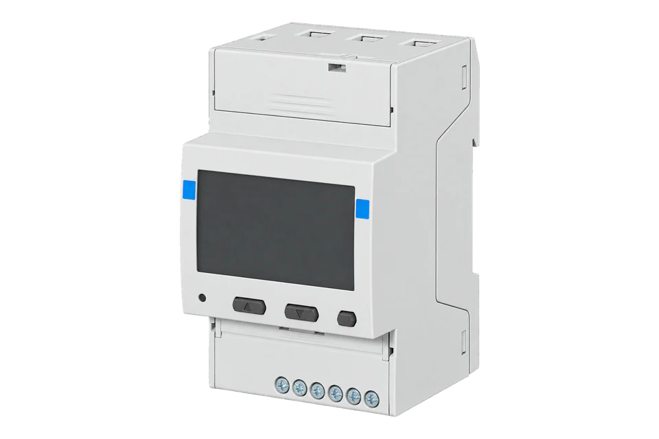
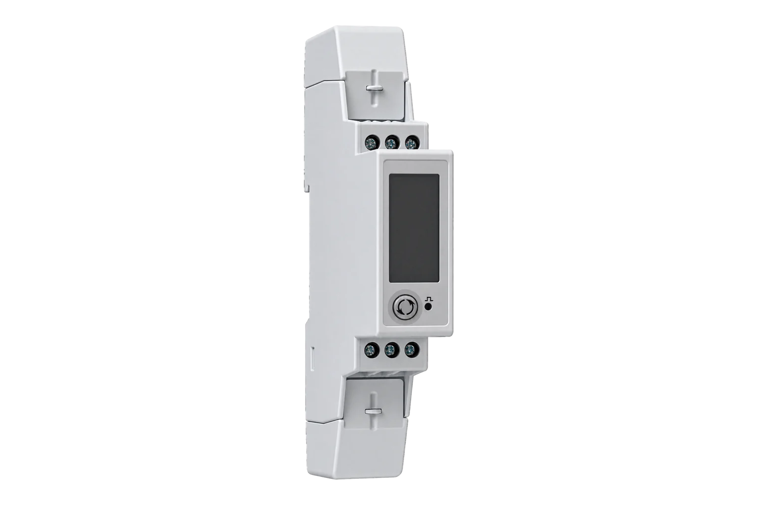
Carlo Gavazzi EM530 / EM540
Energy meter
Compare the 5 A CT-input EM530 with the direct-connected 65 A EM540, then configure RS-485, integer scaling and a read-only voltage check.
- Modbus RTU
Energy meter
Compatibility
Compatible through Modbus RTU
Manufacturer documentation defines a local Modbus measurement path for configuration in the Edge Modbus client.
EM530DINAV53XS1X and EM540DINAV23XS1X standard RS-485 versions. MID counter modes, EM530 333 mV and Rogowski inputs, M-Bus and pulse-output variants require their matching configuration.
Connect it with
-
Modbus Interface ZMB-3XFrom €399 ex VAT Configure Modbus Interface
-
Gateway ZGW-20From €899 ex VAT Configure Gateway


For the S1 communication option
- Modbus
- Edge
- Platforms
Models
| Models | Interface | Route into Edge |
|---|---|---|
| EM530DINAV53XS1X | 5 A CT secondary; RS-485 Modbus RTU | Set the transformer ratio before interpreting primary-side current and power. |
| EM540DINAV23XS1X | Direct current measurement up to 65 A; RS-485 Modbus RTU | Measured load current passes through the meter; no external 5 A CT input. |
| EM530 MV / RG versions | 333 mV sensor or Rogowski input | Different sensor hardware and configuration; do not connect these as a 5 A CT-input model. |
| S1PFA / S1PFB / S1PFC / S1PFD / S1PFE | MID versions with different counter behaviour | Match the precise suffix and protocol ID before relying on import/export totals. |
| M1 / O1 versions | M-Bus / static output | The RS-485 instructions on this page apply to S1, not these ports. |
Specifications
Choose EM530DINAV53XS1X where external CTs with 5 A secondaries measure the circuit. Choose EM540DINAV23XS1X for direct measurement up to 65 A. The March 2026 manual also covers EM530 333 mV and Rogowski inputs, so the family name alone does not identify a compatible sensor. Both selected models have the S1 RS-485 option and share a protocol; one comparison is more useful than two copies of the same register instructions.1
- EM530 selected variant
- EM530DINAV53XS1X: external 5 A CT input1
- EM540 selected variant
- EM540DINAV23XS1X: direct connection up to 65 A1
- Communication
- S1: RS-485 Modbus RTU; M1 and O1 are different output options1
- Read functions
- FC03 and FC04 have the same read effect2
- Maximum read size
- 20 registers per request in protocol V1.112
- Integer order
- Most-significant byte first within each word; least-significant word first for INT32 / UINT32 / UINT642
- Overflow handling
- MSW 0x7FFF indicates the documented EEE overflow, not a valid measurement2
Interface
Documented measurements and integration boundaries for EM530 / EM540.
- Line-to-neutral and line-to-line voltages as scaled signed integers.
- Per-phase current in milliampere units before conversion to A.
- Signed active power and separate imported/exported energy counters.
- Power factor, phase sequence, frequency and demand.
- Part-number identification distinguishes standard, MID and sensor-input variants.
Assessment
EM530DINAV53XS1X and EM540DINAV23XS1X standard RS-485 versions. MID counter modes, EM530 333 mV and Rogowski inputs, M-Bus and pulse-output variants require their matching configuration.
- InteroperabilityWell supported
- An official protocol defines physical addresses, functions, length, signed integer scaling and word order.2
- AccuracySupported with conditions
- The selected variants separate 5 A CT and 65 A direct measurement; sensor ratio and counter mode remain installation-specific.12
- SecurityNot yet assessed
- The retained manual describes local configuration, but does not establish authenticated or encrypted measurement transport.12
- ReliabilityNot yet assessed
- Documented commissioning checks identify incorrect values, but do not establish availability during power or network interruptions.12
- RuggednessNot yet assessed
- The retained operating guide identifies variants and installation procedures, but does not provide a matched environmental rating for the selected order codes.12
- ScalabilitySupported with conditions
- Addressed RS-485 polling and response timing are documented. Start with blocks of at most 20 words; the protocol prose allows 125 words while its request table shows 20, so 20 is a practical starting size rather than a proven hardware maximum.2
Setup
Decode a two-register voltage
Protocol V1.11 lists V L1-N at physical address 0x0000, reference 300001, as INT32 with weight Volt × 10.
- Function and request
- FC04 PDU 04 00 00 00 02; FC03 is also documented for these values.
- Synthetic response words
- 08 FC 00 00: low word 0x08FC followed by high word 0x0000.
- Calculation
- Raw 2300 × 0.1 = 230.0 V. Decode signed INT32, not float32.
- Invalid value
- A high word of 0x7FFF denotes overflow; do not plot it as a voltage.
Acceptance: These bytes are an independent decoder example, not a captured device response. Accept the installed measurement only when it agrees with the simultaneous display and the configured wiring system.
-
Match the input and order code
Record the full label. This guide compares EM530DINAV53XS1X and EM540DINAV23XS1X. For an EM530, confirm AV5 rather than MV or RG. For an EM540, confirm the circuit is within the direct-input rating.
-
Configure the measurement system
Confirm phase association and wiring topology. Set the external CT ratio only on the appropriate EM530. The MID procedure differs from the standard X model; the manual limits resetting that ratio to before the accumulated energy exceeds 1 kWh.
-
Match the serial connection
Use the instrument’s configured address, speed, parity and stop bits. Follow its A-/B+/GND and termination instructions, including the T terminal at the last instrument. Start with one meter and a single read.
-
Read phase voltage
Request FC04 physical address 0, quantity 2. Decode signed INT32 with the low word first and multiply by 0.1 V. Reject the documented overflow pattern before applying scaling.
-
Check direction and expand carefully
Compare voltage, each phase current and total active power with the display under a known load. Select energy counters for the exact suffix. Start with complete values in blocks of at most 20 words within documented address ranges, then expand after checking responses. Keep configuration and reset writes out of connection tests.
Common questions
- Can I use the same CT with every EM530?
- No. AV5 identifies the 5 A CT-input model covered here. The current manual separately identifies MV 333 mV inputs and RG Rogowski inputs. The sensor and meter input must be selected together.2
- Why does the value look wrong when decoded as a float?
- The main measurement block uses integers with explicit weights. Voltage uses INT32 and a factor of 0.1; current uses INT32 and 0.001 A. The low word comes first. Selecting float32 or high-word-first produces a different number even when communication succeeds.2
- Are FC03 and FC04 interchangeable here?
- For the documented read values, the manufacturer states they have the same effect. The physical address is unchanged. This is specific to this protocol and should not be copied to unrelated meters.2
- Why does import energy increase during export?
- Check the exact suffix and counter mode before assuming a wiring fault. Some MID variants use absolute counters and others bidirectional counters. Confirm active-power direction and the matching energy definition in the protocol.2
- Is there an Edge template to import?
- This guide supplies a documented manual read and commissioning procedure. It does not add a preconfigured download or claim that an installation has been tested. Configure the required points in the Edge Modbus client and verify them against the meter.2
Related devices



Sources
- EM530 / EM540 user manual, 13 March 2026 (opens in a new tab) (PDF)
- EM530 / EM540 Modbus protocol V1.11, 7 August 2025 (opens in a new tab) (PDF)
Further reading
Product names and trademarks belong to their owners. Publication does not imply endorsement or a commercial relationship.