Carlo Gavazzi ET340
Three-phase energy transducer
The ET340 is a three-module DIN-rail energy transducer for three-phase loads up to 65 A, wired directly without current transformers and powered from the measured voltage. It has no display: readings leave the unit only through its Modbus RTU port, which is on screw terminals and two parallel RJ45 sockets. Carlo Gavazzi reads it with the shared EM300/ET300 protocol, where each value has a physical word address, a scale factor and a signed 32-bit format sent low word first. Voltage at 0x0000 arrives in tenths of a volt, and the identification code at 0x000B reads 345.

Compatibility
Compatible with EpiSensor Edge over Modbus RTU
The ET340 is compatible with EpiSensor Edge over its RS-485 Modbus RTU port, read through a ZMB-31 Modbus Interface or a Gateway serial port. Carlo Gavazzi publishes the register map with physical addresses, data types, word order and scaling for read functions 03 and 04.
ET340-DIN AV2 3 X S1 X, using the EM300/ET300 communication protocol version 2 revision 17. Site check: read the identification code at 0x000B and expect 345 before adding points. The datasheet documents RS-485 Modbus RTU only, with no Ethernet or Modbus TCP port. Read-only monitoring: no writes to the configuration, serial-port or reset registers.
Connect it with
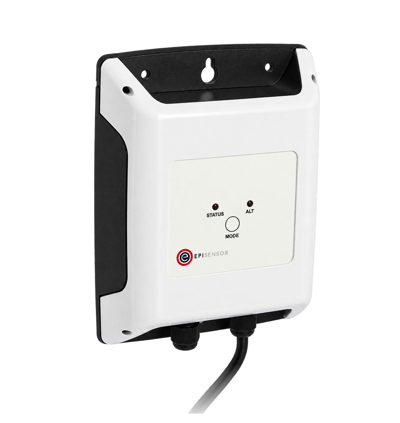
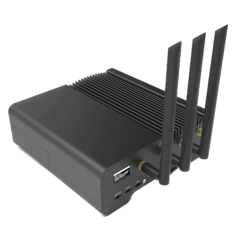
For a transducer in a distribution board where a wireless link avoids running a data cable back to the Gateway
- Modbus
- Wireless
- Edge
- Platforms
When the Gateway sits near the transducer, or several meters share one wired RS-485 bus
- Modbus
- Edge
- Platforms
Models
| Models | Interface | Route into Edge |
|---|---|---|
| ET340-DIN AV2 3 X S1 X | Direct 5(65) A inputs, 208 to 400 V L-L, self-powered; RS-485 Modbus RTU on terminals 7 to 10 and two RJ45 sockets; front optical port; one tariff digital input | The exact scope of this guide. Identification code 345 at 0x000B. |
| ET330-DIN AV5 or AV6 3 L/H S1 X | Current-transformer inputs, in the same protocol document; identification code 335 (AV5) or 336 (AV6) | Same register layout, but CT and VT ratios are set on the meter and its electrical limits differ. Use the ET330 datasheet for wiring. |
| EM340-DIN AV2 3 X S1 X and PF variants | The same direct 65 A inputs with a display and keys; identification code 341 | Shares the map, but the protocol lists the run-hour meter, neutral current and per-phase exported energy for the ET series and not for the EM340. See the EM340 guide for that model. |
Specifications
The ET340 measures a three-phase load up to 65 A directly, with no current transformers, and powers itself from the measured voltage. It has no display or keys: two LEDs show power, communication and a 1000 pulse per kWh flash, and the measurements are read over Modbus RTU on the RS-485 screw terminals, either RJ45 socket or the front optical port. All of these are the same Modbus port in parallel, so use one at a time.23
- Order code
- ET340-DIN AV2 3 X S1 X: range AV2, system 3, self power supply X, output S1 (RS-485 Modbus port), option X (none). S1 is the only output listed.2
- Measuring inputs
- 208 to 400 V L-L AC, 45 to 65 Hz; direct current measurement 5(65) A (Ib 5 A, Imax 65 A, Imin 0.25 A, start-up 20 mA).23
- Accuracy
- Active energy class 1 (EN 62053-21), reactive energy class 2 (EN 62053-23); current ±0.5% RDG from 0.2 Ib to Imax; phase-neutral voltage ±0.5% RDG, phase-phase ±1% RDG.2
- RS-485
- Modbus RTU slave on terminals 7 (T), 8 (B+), 9 (A-) and 10 (GND), and two RJ45 sockets (pin 4 B+, pin 5 A-, pin 8 GND). Address 1 to 247 (default 1); 9.6, 19.2, 38.4, 57.6 or 115.2 kbit/s; even or no parity. The protocol gives 9600 bit/s, no parity and 1 stop bit as defaults.12
- Bus
- 1/8 unit load, up to 247 transceivers on one bus, a repeater beyond 1000 m. Terminate the last device by linking A- (9) to T (7). Data refresh 1 s; 50 words per read request.23
- Digital input
- One voltage-free contact on terminals 11 and 12 for tariff selection: open is tariff 1, closed is tariff 2.23
- Supply
- Self-powered from the measuring inputs, 208 to 400 V L-L -20% +20%; at most 1 W and 10 VA.2
- Approvals
- CE; safety EN 62052-11; metrology EN 62053-21.2
- Housing
- 3 DIN modules, 54 × 90 × 63 mm, DIN-rail mounting, sealing covers included. IP20 front and terminals. Measuring terminals 2.5 to 16 mm²; other terminals 1.5 mm².23
- Environment
- Operating -20 to +65 °C, 0 to 90% RH non-condensing at 40 °C, indoor; storage -30 to +80 °C. Overvoltage category III.2
Interface
Documented measurements and integration boundaries for ET340.
- Addresses are physical word addresses sent in the frame: L1-N voltage is printed as Modicon 300001 and physical 0000h, and goes on the wire as 0x0000. FC03 and FC04 return the same values.
- INT32 values are two registers, low word first, with each word high byte first. Signed values use two's complement.
- L1-N, L2-N and L3-N voltage at 0x0000, 0x0002 and 0x0004; L1-L2, L2-L3 and L3-L1 at 0x0006, 0x0008 and 0x000A: INT32, volts × 10.
- L1, L2 and L3 current at 0x000C, 0x000E and 0x0010: INT32, amperes × 1000. Neutral current at 0x0098, same format, listed for the ET series and EM330.
- L1 to L3 active power at 0x0012 to 0x0016 (W × 10), apparent power at 0x0018 to 0x001C (VA × 10) and reactive power at 0x001E to 0x0022 (var × 10): INT32.
- System values: V L-N at 0x0024 and V L-L at 0x0026 (V × 10), W at 0x0028, VA at 0x002A and var at 0x002C (× 10), demand W at 0x0038 and peak demand W at 0x003A (W × 10): INT32.
- Power factor L1, L2, L3 and system at 0x002E to 0x0031: one register each, INT16, PF × 1000. A negative value means exported active power.
- Phase sequence at 0x0032 (INT16; the protocol gives 0 as L1-L2-L3 and 1 as L1-L3-L2) and frequency at 0x0033 (INT16, Hz × 10).
- Imported energy: kWh(+) total at 0x0034, kvarh(+) total at 0x0036, partial kWh(+) at 0x003C, kWh(+) per phase at 0x0040 to 0x0044, tariff 1 and tariff 2 at 0x0046 and 0x0048. All INT32, kWh × 10 or kvarh × 10.
- Exported energy: kWh(-) total at 0x004E, kvarh(-) total at 0x0050 and kWh(-) per phase at 0x0060 to 0x0064 (ET series only): INT32, × 10. They count only in measurement mode B.
- Run-hour meter at 0x005A: INT32, hours × 100, ET series and EM330. Rows marked not available in the table (THD, kVAh, tariffs 3 to 8) read 0.
- Identity: identification code at 0x000B (UINT16, 345 for the ET340), firmware version and revision at 0x0302 and 0x0303, serial number as ASCII in the low byte of 0x5000 to 0x5006. Read 0x000B as a single register.
- Configuration from 0x1000, the serial port from 0x2000 and the reset commands from 0x4000 are writable, including a reset of the total energy counters on X-option meters. Keep them out of a monitoring poll.
Assessment
ET340-DIN AV2 3 X S1 X, using the EM300/ET300 communication protocol version 2 revision 17. Site check: read the identification code at 0x000B and expect 345 before adding points. The datasheet documents RS-485 Modbus RTU only, with no Ethernet or Modbus TCP port. Read-only monitoring: no writes to the configuration, serial-port or reset registers.
- InteroperabilityWell supported
- Carlo Gavazzi documents Modbus RTU on the S1 port and publishes FC03/FC04, physical and Modicon addresses, register lengths, data types, low-word-first word order, scale factors and an identification code for the ET340.12
- AccuracySupported with conditions
- Class 1 active and class 2 reactive energy with per-phase voltage, current, power, power factor and per-phase energy, measured directly up to 65 A. The measurement mode decides whether direction is respected and exported energy is counted.12
- SecurityNot yet assessed
- The protocol states the password register always reads 0 on the ET series, and configuration, serial-port and reset registers, including a total-energy reset on X-option meters, are writable over the port.1
- ReliabilitySupported with conditions
- The protocol defines exception codes, a 500 ms answering time, a 40 ms minimum gap between queries, a repeat-then-fail rule for missing replies and an overflow marker (words FFFF 7FFF). Energy is saved to non-volatile memory each time its least significant digit changes.12
- RuggednessSupported with conditions
- Rated -20 to +65 °C operating, IP20 front and terminals, overvoltage category III, with 4 kV insulation between the measuring inputs and the serial output. Indoor use inside a suitable enclosure.2
Setup
Read L1-N voltage from physical address 0x0000
EM300/ET300 communication protocol version 2 revision 17, Table 2.4-1, lists V L1-N at Modicon address 300001, physical address 0000h, two words, INT32, value weight Volt*10. Use that map as the starting point and check the first reading before adding more points.
- Request
- 01 04 00 00 00 02 71 CB: Modbus address 1, FC04, physical address 0x0000, two registers, RTU CRC. FC03 gives the same value: 01 03 00 00 00 02 C4 0B.
- Address convention
- Send the physical address as printed: 0x0000 is the zero-based PDU address 0. A client that numbers registers from one shows it as input register 1 (300001) for FC04 or holding register 1 (400001) for FC03. Do not send 300001, or 1, as the PDU address.
- Synthetic response
- 01 04 04 08 FC 00 00 39 D4: four data bytes, low word 08 FC first, then high word 00 00.
- Decode
- INT32 with the low word first and each word high byte first: 0x000008FC = 2300. The weight is Volt*10, so 2300 ÷ 10 = 230.0 V. A client that takes the high word first reads 0x08FC0000 = 150,732,800, which would show as 15,073,280.0 V.
- Overflow
- Words FFFF 7FFF are the overflow value 0x7FFFFFFF. Treat them as missing data, not as a reading.
- Acceptance
- The ET340 has no display. Keep the point when it agrees with L1-N voltage measured at the terminals, or with another meter on the same supply, at the same time. If it does not, check the address, word order and that 0x000B reads 345.
Acceptance: The response bytes are a synthetic decoder check, not a captured meter reply. Record the protocol revision and the firmware version from 0x0302 and 0x0303 with the configuration.
-
Identify the transducer
Read the order code on the side label: ET340-DIN AV2 3 X S1 X. The side label also numbers the RS-485 terminals 7 (T), 8 (B+), 9 (A-) and 10 (GND) and the tariff input 11 and 12.
-
Find the serial settings
The ET340 has no display, so take the address, baud rate and parity from the commissioning record or the configuration tool. Out of the box the protocol gives address 1, 9600 bit/s, no parity and 1 stop bit. Enter the same values in the Edge serial client.
-
Wire the RS-485 pair
Connect A- to terminal 9, B+ to 8 and the common to GND on 10, or use one RJ45 socket. The screw terminals, both RJ45 sockets and the optical port are one port in parallel, so connect only one master. Link A- (9) to T (7) on the last device on the bus.
-
Make two reads
Read the identification code at 0x000B, one register, and expect 345. Then read L1-N voltage at 0x0000 for two registers, decode it low word first as in the worked read below, and compare it with a voltage measured at the terminals.
-
Check wiring and counting mode
Read the wrong-connection status at 0x1105: every bit at 0 means the voltage sequence and current directions are right. Read the measurement mode at 0x1103 (0 is A, 1 is B) before relying on exported energy, then add current, power and energy points from the same table.
Common questions
- Why does voltage read as millions of volts?
- The client is taking the high word first. The EM300/ET300 protocol sends INT32, UINT32 and UINT64 values least significant word first, with each word high byte first. Swap the two registers, then apply the scale: 2300 at 0x0000 is 230.0 V.1
- How do I check readings when the ET340 has no display?
- Start with the identification code at 0x000B, which reads 345 on the ET340, then compare voltage with a measurement at the terminals and power with a known load. The wrong-connection status at 0x1105 flags reversed phases and a wrong voltage sequence, and reads 0 when the wiring is right.12
- Does the ET340 support Modbus TCP?
- Not on the transducer itself. The order code lists one output, S1, the RS-485 Modbus RTU port, and the datasheet describes no Ethernet port. Read it over RS-485 through a ZMB-31 Modbus Interface or the Gateway serial port.2
- Why does exported energy stay at zero?
- Check the measurement mode at 0x1103. In mode A (easy connection) the ET340 counts total energy without regard to direction, current and power are always positive and kWh(-) does not increase. Mode B keeps imported and exported energy apart. Have the installer change the mode with the configuration tool if export must be counted.13
- Can I use the RJ45 sockets and the screw terminals at the same time?
- No. Carlo Gavazzi states that the screw terminals, both RJ45 sockets and the optical port are the same Modbus port in parallel, and only one can be used at a time. The two RJ45 sockets let you daisy-chain the bus with patch leads: pin 4 is B+, pin 5 is A- and pin 8 is GND.23
- Is the ET340 a billing meter?
- The datasheet gives class 1 active energy to EN 62053-21 and lists CE as the only approval, with no MID certification. Treat it as a monitoring and cost-allocation transducer and use an approved meter where billing is required.2
Related devices
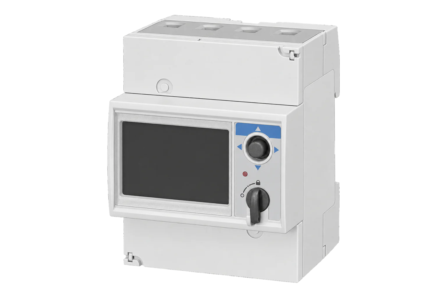
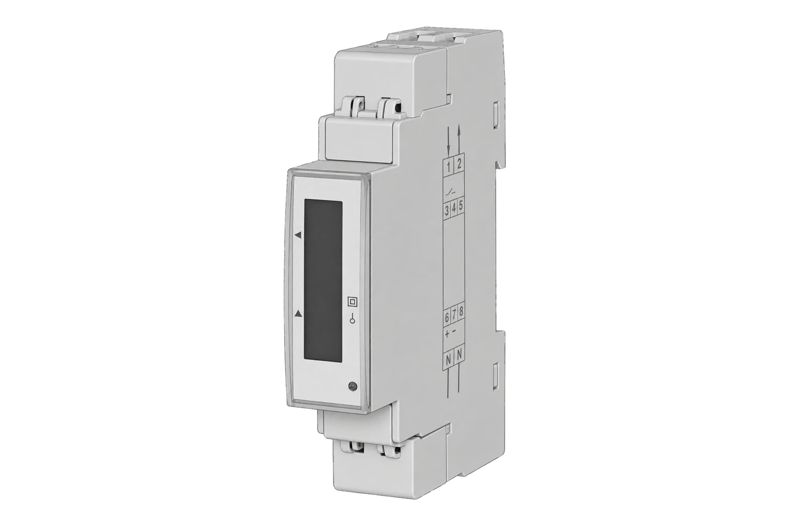

Sources
- EM300 series and ET300 series communication protocol, version 2 revision 17 (5 July 2021) (opens in a new tab) (PDF)
- ET340 energy transducer datasheet (ET340 DS 310518), order code, specifications and wiring diagrams (opens in a new tab) (PDF)
- ET340 installation and use instructions (code 8021626), English section (opens in a new tab) (PDF)
Further reading
- ToolModbus register address translator
- ToolModbus data decoder
- GuideModbus commissioning over RS-485
- GuideEM340 DIN AV2 3 X S1 X: the same 65 A inputs with a display
- GuideEM210 RS-485: the same low-word-first INT32 format
- ToolRS-485 termination and bias
- ManufacturerCarlo Gavazzi devices
- ProtocolModbus devices and register maps
- CategoryEnergy meters
Product names and trademarks belong to their owners. Publication does not imply endorsement or a commercial relationship.