Circutor CEM-C31
Three-phase energy meter
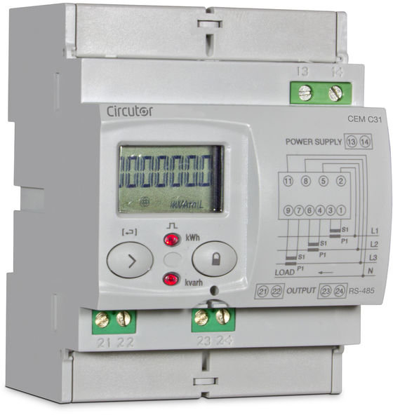
The CEM-C31 is Circutor's three-phase DIN-rail energy meter for current transformers with a 5 A secondary. The CEM-C31-485-T1 and CEM-C31-485-DS add an RS-485 port running Modbus RTU, and each comes in a MID version with class B active energy; the CEM-C31-485-T1-MID is code Q23522. Circutor's instruction manual publishes the map in hexadecimal: energy counters in Wh and varh, phase voltages in tenths of a volt, currents in hundredths of an amp and power in W, var and VA, each value in two registers. Circutor now names the CEM-D311-MID (Q23612) as the replacement for Q23522, so this guide is mainly for reading meters that are already installed.
Compatibility
Compatible with EpiSensor Edge over Modbus RTU
The CEM-C31-485-T1 and CEM-C31-485-DS, with or without MID, are compatible with EpiSensor Edge over their RS-485 Modbus RTU port, read through a ZMB-31 Modbus Interface or a Gateway serial port. Circutor's manual lists FC03 and FC04 reads and a hexadecimal map of energy, voltage, current and power registers with sizes and units, and its own frames confirm the address convention.
CEM-C31-485-T1 and CEM-C31-485-DS, MID or not (the CEM-C31-485-T1-MID is code Q23522), using instruction manual M017B01-03-23A. The CEM-C31-T1 has an optical port instead of RS-485 and is not covered. Site check: compare the first voltage read with the display; the same read shows the word order. Read-only monitoring: no FC10 writes and no FC05 partial-energy reset.
Connect it with
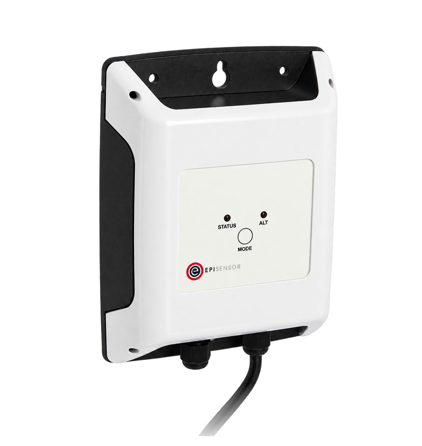
For a meter in a distribution board where a wireless link avoids running a data cable back to the Gateway
- Modbus
- Wireless
- Edge
- Platforms
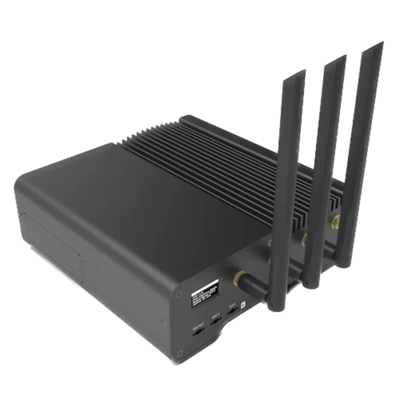
When the Gateway sits near the meter, or several meters share one wired RS-485 bus
- Modbus
- Edge
- Platforms
Models
| Models | Interface | Route into Edge |
|---|---|---|
| CEM-C31-485-T1 and CEM-C31-485-T1-MID (Q23522) | Three CT inputs for .../5 A; RS-485 Modbus RTU on terminals 23 B(-) and 24 A(+); one optocoupler pulse output on 21 and 22 | Read the energy and instantaneous value registers on the serial path. |
| CEM-C31-485-DS and CEM-C31-485-DS-MID | The same RS-485 port, with a digital input on 21 and 22 instead of the pulse output, set to select the tariff or to count pulses | Same read path. The tariff energy registers at 0x0100 to 0x0136 and the pulse counts at 0x0180 and 0x0182 exist only on this version. |
| CEM-C31-T1 and CEM-C31-T1-MID | Optical service port to EN 62056-21 and a pulse output; no RS-485 terminals | No RS-485 port to wire. This guide does not cover the optical port or Circutor's CEM M-RS485 add-on module. |
| CEM-D311-MID (Q23612) | Circutor's named replacement for Q23522 | A different product with its own documentation. Do not apply this register map to it without checking its manual. |
Specifications
A four-module DIN-rail energy meter for three-phase four-wire circuits measured through current transformers. It counts imported and exported active energy and reactive energy by quadrant, and shows per-phase voltage, current, power and power factor. The order code fixes the communication option, the input or output on terminals 21 and 22, and whether the meter records 2 quadrants, 4 quadrants or absolute energy.12
- Versions
- CEM-C31-T1, CEM-C31-485-T1 and CEM-C31-485-DS, each with a MID version. CEM-C31-485-T1-MID is code Q23522; Circutor names the CEM-D311-MID (Q23612) as its replacement.12
- Current inputs
- Through current transformers, 5(10) A: reference current 5 A, maximum 10 A, minimum 0.05 A, starting current 0.010 A. The primary and secondary ratios are set in the metrological setup menu.12
- Voltage inputs
- Three-phase four-wire, 3 × 57/100 V to 3 × 230/400 V depending on the version; 50 Hz, 60 Hz or automatic 50/60 Hz by order code. The manual also draws a single-phase connection.2
- Accuracy
- MID versions: active energy class B to EN 50470-3. Other versions: class 1 to IEC 62053-21. Reactive energy class 2 to IEC 62053-23.12
- Auxiliary supply
- Terminals 13 and 14, 230 V ~ or 230/400 V ~ depending on the version, ±20 %, 50 to 60 Hz, under 2 W. Check the label on the installed meter.12
- RS-485
- 485 versions only: terminal 23 B(-) and 24 A(+). Modbus RTU, peripheral address 1 to 254 (default 1), 9600, 19200 or 38400 bit/s (default 9600), 8 data bits with no, even or odd parity and 1 or 2 stop bits (default 8N1). Up to 32 devices and 1200 m of shielded twisted pair.2
- Inputs and outputs
- 485-T1: optocoupler pulse output on 21 (collector) and 22 (emitter), up to 24 V and 50 mA, programmable for kWh or kvarh. 485-DS: self-powered 5 V digital input on 21 and 22 for tariff selection or pulse counting.2
- Display
- LCD up to 999999.9 kWh, two buttons (the setup button can be sealed) and two test LEDs at 20000 imp/kWh and 20000 imp/kvarh.12
- Environment
- Operating -25 to +70 °C, storage -35 to +80 °C, 5 to 95 % relative humidity without condensation, up to 2000 m.2
Interface
Documented measurements and integration boundaries for CEM-C31.
- All map addresses are hexadecimal and go on the wire as printed: 0x0732 is sent as 07 32 (decimal 1842). Read with FC03 or FC04; the map's writes use FC10 and the partial-energy reset uses FC05. Request exactly the number of registers the variable occupies.
- Phase 1, 2 and 3 voltage at 0x0732, 0x0734 and 0x0736: two registers each, volts with one decimal place, so divide by 10. Table 20 gives these as primary values, so the programmed transformer ratios are already applied.
- Phase 1, 2 and 3 current at 0x0738, 0x073A and 0x073C: two registers each, amps with two decimal places, so divide by 100.
- cos φ for phases 1, 2 and 3 at 0x073E, 0x0740 and 0x0742: two registers each with two decimal places. The map has no total power factor and no frequency register.
- Active power for phases 1, 2 and 3 at 0x0746, 0x0748 and 0x074A, and total active power at 0x074C: two registers each in W. Reactive power follows at 0x074E to 0x0754 in var and apparent power at 0x0756 to 0x075C in VA, total last in each group.
- Imported active energy at 0x0000 and exported active energy at 0x0002: two registers each in Wh. Reactive energy by quadrant at 0x0004 (Q1), 0x0006 (Q2), 0x0008 (Q3) and 0x000A (Q4) in varh. Exported energy, Q2 and Q3 are marked for the 4-quadrant version only.
- Partial counters repeat the same order from 0x0030 to 0x003A. They can be cleared from the setup menu and by FC05 to 0x0800, so use the totals from 0x0000 for consumption records.
- On the CEM-C31-485-DS with the input set to tariff, tariff 1 energy starts at 0x0100 and tariff 2 at 0x010C, total then partial, in the same order as the totals.
- Identity: the model description at 0xF010 is six registers of ASCII, coded as in Table 24 (one character gives 2 quadrants, 4 quadrants or ABS). Serial number at 0x0060, firmware version at 0x0050 to 0x0052, total operating time in seconds at 0x00C6.
- Configuration is readable and writable with FC10: transformer ratios at 0x044C to 0x0452, Modbus address at 0x03E8, speed at 0x03E9 and frame format at 0x03EA. Keep them out of a monitoring poll.
Assessment
CEM-C31-485-T1 and CEM-C31-485-DS, MID or not (the CEM-C31-485-T1-MID is code Q23522), using instruction manual M017B01-03-23A. The CEM-C31-T1 has an optical port instead of RS-485 and is not covered. Site check: compare the first voltage read with the display; the same read shows the word order. Read-only monitoring: no FC10 writes and no FC05 partial-energy reset.
- InteroperabilitySupported with conditions
- Circutor documents Modbus RTU on RS-485 with FC03 and FC04 reads, a hexadecimal map with sizes, units and decimal places, and example frames that confirm the address convention. The manual does not state the word order of 32-bit values or whether power is signed, so the first read is compared with the display.2
- AccuracySupported with conditions
- Class B active energy on the MID versions and class 1 on the others, class 2 reactive energy, Wh and varh counters by quadrant and per-phase voltage, current and power. Accuracy also depends on the external CTs and the programmed ratio, export is counted only on the 4-quadrant version, and the map has no frequency.12
- SecurityLimited
- The setup button and terminal covers can be sealed, but the Modbus interface has no authentication: FC10 changes the address, serial settings and transformer ratios, and FC05 clears the partial counters. Keep the bus private and send reads only.2
- ReliabilitySupported with conditions
- The manual gives the EN 50470 and IEC 62053 standards, 4 kV insulation and 6 kV impulse tests, and the product page says the meter flags bad connections on screen and keeps its energy through them. No exception codes or response times are given; treat failed reads as missing data.12
- RuggednessSupported with conditions
- Rated -25 to +70 °C, 5 to 95 % humidity and up to 2000 m, with IP51 when installed and IP40 at the terminals. It is a DIN-rail meter for a panel or enclosure.2
- ScalabilitySupported with conditions
- Up to 32 devices and 1200 m per bus, peripheral addresses 1 to 254 and speeds up to 38400 bit/s. Consecutive registers can be read in one request, but the manual gives no maximum request length.2
Setup
Read phase 1 voltage from hexadecimal address 0x0732
CEM-C31 instruction manual M017B01-03-23A, Table 20, lists phase 1 voltage at 0x0732, 32 bits, in volts with one decimal place. Use that map as the starting point and compare the result with the display.
- Request
- 01 04 07 32 00 02 D1 70: peripheral address 1, FC04, start address 0x0732, two registers, RTU CRC. FC03 gives the same value: 01 03 07 32 00 02 64 B0.
- Address convention
- The manual states that every map address is hexadecimal, and its own write example sends 03E8 for the Modbus address register that Table 25 lists at 0x03E8. Send 0x0732, decimal 1842, as the zero-based PDU address. A client that numbers registers from one shows it as 1843 (31843 for FC04, 41843 for FC03). Do not send decimal 732.
- Synthetic response
- 01 04 04 00 00 08 FC FC 05: four data bytes, 00 00 then 08 FC.
- Decode
- The manual does not print the word order of its 32-bit values. A phase voltage in tenths of a volt fits in one 16-bit word, so one word reads zero. Here the zero word comes first, so the meter sends the high word first: 0x000008FC = 2300, and 2300 / 10 = 230.0 V. If the zero word comes second, set the low word first for every 32-bit point.
- Acceptance
- Keep the point when it agrees with phase 1 voltage on the meter display at the same time. If it does not, check the address, the voltage transformer ratio and whether the client has added one to the address before adding more points.
Acceptance: The response bytes are a synthetic decoder check, not a captured meter reply. A real reply must agree with the display before current, power and energy points are enabled.
-
Identify the meter
Read the model on the label and confirm a 485 version: CEM-C31-485-T1 or CEM-C31-485-DS, with or without MID. Note whether it records 2 quadrants, 4 quadrants or absolute energy, and confirm the CT ratio with the installer.
-
Read the serial settings from the setup menu
A long press opens the general setup menu, which shows the peripheral address, speed and frame format (for example 8n1). Enter the same values in the Edge serial client or the ZMB-31 and leave the meter's own settings unchanged.
-
Wire the RS-485 pair
Connect A(+) to terminal 24 and B(-) to terminal 23 with shielded twisted pair, keep the bus under 1200 m and 32 devices, and give each meter its own peripheral address.
-
Make one voltage read
Send FC04 to address 0x0732 for two registers, as in the worked read below. One of the two words reads zero; that tells you the word order. Divide by 10 and compare with phase 1 voltage on the display.
-
Add the points you need
Add current, power and the energy counters with the same word order. Use the total counters from 0x0000 rather than the resettable partial counters, and keep FC10 and FC05 out of the polling configuration.
Common questions
- Is 0x0732 register 732 or 1842?
- 1842. Circutor states that all Modbus map addresses in the CEM-C31 manual are hexadecimal, and its example frames send them as printed. Enter 0x0732 in a client that takes zero-based addresses. A client with one-based labels calls the same register 1843, or 31843 for FC04.2
- Which word of a 32-bit value comes first?
- The manual does not say. Read a phase voltage first: in tenths of a volt it fits in one word, so the other word is zero and shows which half is the high word. Apply the same order to current, power and energy, and check one energy counter against the display.2
- Why does exported energy read zero or return an error?
- Exported active energy at 0x0002 and Q2 and Q3 reactive energy are marked for the 4-quadrant version only. A 2-quadrant meter records consumed energy only, and an ABS meter adds consumed and generated energy into one imported counter. The model description at 0xF010 and the label show which version is installed.2
- Where are frequency and total power factor?
- Table 20 lists voltage, current, cos φ and active, reactive and apparent power per phase, plus total power, but no frequency and no total power factor register. If you need a total power factor, calculate it in Edge from total active power at 0x074C and total apparent power at 0x075C.2
- Which serial number address is right?
- Table 23 lists the serial number at 0x0060 as 32 bits, while the read example in section 7.2.2.1 requests it at 0x2710. Use the table address, and do not rely on the serial number to identify a meter until one of them agrees with the label.2
- Is the CEM-C31-485-T1-MID still sold?
- Circutor's product page for Q23522 says to check availability and names the CEM-D311-MID (Q23612) as its replacement. That model has its own documentation; do not assume it uses this map.1
Related devices
Sources
- CEM-C31-485-T1-MID product page, code Q23522 (opens in a new tab)
- CEM-C31 instruction manual M017B01-03-23A, communications, Modbus variables and technical features (opens in a new tab) (PDF)
Further reading
Product names and trademarks belong to their owners. Publication does not imply endorsement or a commercial relationship.