Carlo Gavazzi WM15
Panel-mounted power analyser
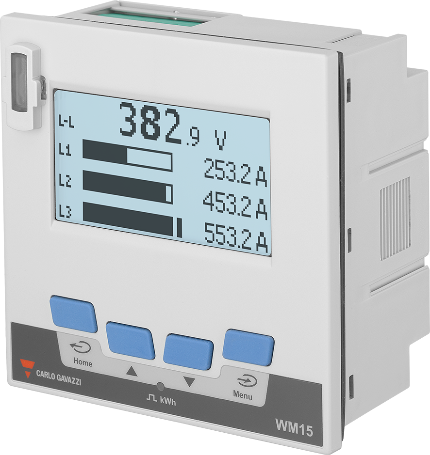
The WM15 is a three-phase power analyser for a 96 × 96 mm panel cut-out, measuring through external ../5 A current transformers with a backlit matrix display and four keys. Three output options exist: OX has only the static output, OM adds an M-Bus port and OS adds a 2-wire RS-485 port running Modbus RTU. Carlo Gavazzi's communication protocol gives every measurement a physical word address, a scale factor and a data type: most values are signed 32-bit integers sent low word first, so L1-N voltage at 0x0000 arrives in tenths of a volt with the low word in the first register.
Compatibility
Compatible with EpiSensor Edge over Modbus RTU
The WM15 is compatible with EpiSensor Edge over the RS-485 Modbus RTU port of its OS versions, read through a ZMB-31 Modbus Interface or a Gateway serial port. Carlo Gavazzi publishes the register map with FC03 and FC04, physical and Modicon addresses, data types, low-word-first word order and scale factors.
WM15 96 AV5 3 X OS (self-powered, with or without the PFB MID option) and WM15 96 AV5 3 H OS (auxiliary supply), using the WM15 communication protocol version 1.2 of 20 December 2019. OX versions have no communication port, and OM versions carry M-Bus, which this guide does not cover. Site check: read the identification code at 0x000B and compare the first voltage read with the display. Read-only monitoring: no writes to the password, system, CT ratio, serial port or reset registers.
Connect it with
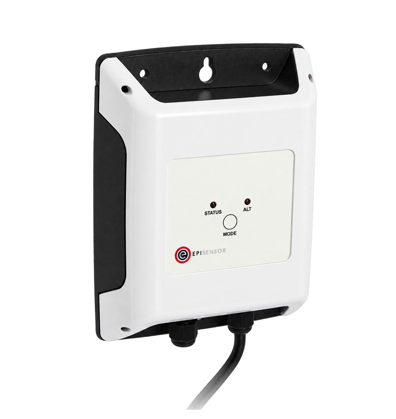
For an analyser in a switchboard where a wireless link avoids running a data cable back to the Gateway
- Modbus
- Wireless
- Edge
- Platforms
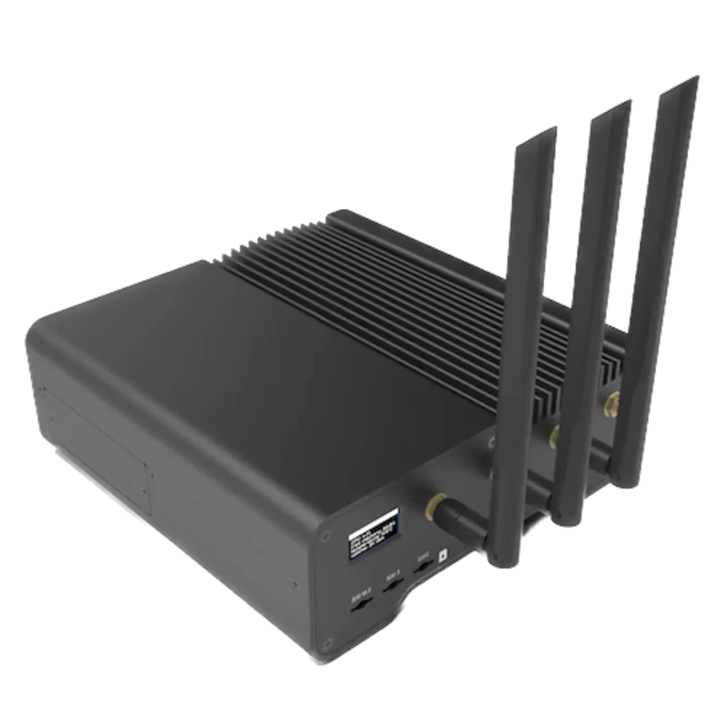
When the Gateway sits near the analyser, or several meters share one wired RS-485 bus
- Modbus
- Edge
- Platforms
Models
| Models | Interface | Route into Edge |
|---|---|---|
| WM15 96 AV5 3 X OS X, X05, XCN, XKR, XCN05 and XKR05 | Supplied from the measured voltage, 120 to 240 V L-N, 208 to 415 V L-L; 5 A CT inputs; RS-485 Modbus RTU on terminals 9 to 12; static output on 7 and 8. X05 is the class 0.5S option; CN and KR change the display language. | Read Table 4.1-1 with FC03 or FC04 on the serial path. Identification code 1680 at 0x000B for WM1596AV53XOSX. |
| WM15 96 AV5 3 X OS PFB | MID-certified self-powered version for 3 × 230 (400) V, 50 Hz, three-phase systems with or without neutral; the same RS-485 port | Same read path and addresses. Identification code 1681. The CT ratio register is read-only on MID versions; keep the poll read-only. |
| WM15 96 AV5 3 H OS X and XCN | 120 to 240 V AC/DC auxiliary supply; 120 to 347 V L-N, 208 to 600 V L-L; the same RS-485 port | Same read path and addresses. Identification code 1684 for WM1596AV53HOSX. |
| WM15 96 AV5 3 X OX and X OM | OX: static output only. OM: static output and an M-Bus port (EN 13757-3) | No Modbus path. This register map applies only to OS versions. |
Specifications
The WM15 is a three-phase power analyser for switchboards: it measures voltage, current, power, power factor, frequency, THD up to the 15th harmonic and active, reactive and apparent energy through external 5 A current transformers, and shows them on a 128 × 64 dot backlit display with current bar graphs. Every version has a static output for pulses or an alarm; the OS versions add RS-485 Modbus RTU and the OM versions M-Bus. An optical port on the front takes Carlo Gavazzi's OptoProg for configuration.23
- Order code
- WM15 96 AV5 3, then supply X (self-powered, 415 V L-L) or H (auxiliary supply, 600 V L-L), then output OX (static output), OM (static output and M-Bus) or OS (static output and RS-485), then option X (class 1), PFB (MID, class B), X05 (class 0.5S) or a CN or KR display-language variant.23
- Measuring inputs
- Direct voltage connection: self-powered 120 to 240 V L-N, 208 to 415 V L-L; auxiliary-supply version 120 to 347 V L-N, 208 to 600 V L-L; MID 230 V L-N, 400 V L-L at 50 Hz. Current through CTs: 5 A rated, 6 A maximum, 10 mA start-up, CT ratio up to 2000. 45 to 65 Hz.2
- Systems
- Single-phase 2-wire, two-phase 3-wire, three-phase 3-wire and 4-wire, and the wild-leg four-wire delta. MID versions: three-phase with neutral, and three-phase without neutral (ARON).2
- Accuracy
- Active energy class 1 (EN 62053-21) and class B (EN 50470-3) on MID versions; class 0.5S (IEC 62053-22) with the 05 option. Reactive energy class 2 (EN 62053-23). Voltage ±0.5% of reading (±0.2% with the 05 option); current ±0.5% of reading from 0.05 In (±0.3%).2
- RS-485
- Modbus RTU on terminals 10 (A-), 11 (B+) and 12 (GND), with terminal 9 linked to B+ on the last device. Address 1 to 247 (default 1); 9.6, 19.2, 38.4, 57.6 or 115.2 kbit/s (default 9.6); no parity or even parity; 1 or 2 stop bits, with 1 fixed under even parity. Registers refresh every 100 ms or faster.12
- Bus
- 1/5 unit load: up to 160 devices and 1000 m before a repeater. Terminate both ends: 120 Ω, ½ W at the master and the B+ to T link on the last WM15. AWG24 balanced pair with a third wire for GND, earthed only at the host.12
- Digital output
- One opto-mosfet output on terminals 7 and 8, for pulses (0.001 to 10 kWh per pulse, 30 or 100 ms) or an alarm; 100 mA maximum.23
- Approvals
- MID (2014/32/EU) on PFB versions; cULus approved (UL 61010); safety EN 61010-1; IEC/EN 61557-12 performance requirements for active power and energy.2
- Housing
- 96 × 96 mm panel mounting, 280 g. Front IP51, terminals IP20; screw terminals 0.05 to 2.5 mm². Overvoltage category III, pollution degree 2.2
- Environment
- Operating -25 to +55 °C; storage -25 to +70 °C; relative humidity below 90% non-condensing at 40 °C.2
Interface
Documented measurements and integration boundaries for WM15.
- Addresses are physical word addresses sent in the frame: L1-N voltage is printed as Modicon 300001 and physical 0000h, and goes on the wire as 0x0000. FC03 and FC04 return the same values.
- INT32 values are two registers, low word first, with each word high byte first. Signed values use two's complement.
- L1-N, L2-N and L3-N voltage at 0x0000, 0x0002 and 0x0004; L1-L2, L2-L3 and L3-L1 at 0x0006, 0x0008 and 0x000A: INT32, volts × 10.
- L1, L2 and L3 current at 0x000C, 0x000E and 0x0010: INT32, amperes × 1000.
- L1 to L3 active power at 0x0012 to 0x0016 (W × 10), apparent power at 0x0018 to 0x001C (VA × 10) and reactive power at 0x001E to 0x0022 (var × 10): INT32.
- System values: V L-N at 0x0024 and V L-L at 0x0026 (V × 10), W at 0x0028, VA at 0x002A and var at 0x002C (× 10): INT32.
- Power factor L1, L2, L3 and system at 0x002E to 0x0031: one register each, INT16, PF × 1000, negative for exported active power. The same four with lead negative and lag positive are at 0x0072 to 0x0075.
- Phase sequence at 0x0032 (INT16: -1 is L1-L3-L2, 0 is L1-L2-L3) and frequency at 0x0033 (INT16, hertz × 10).
- Imported active energy kWh(+) TOT at 0x0034, imported reactive energy kvarh(+) TOT at 0x0036, exported kWh(-) TOT at 0x004E, exported kvarh(-) TOT at 0x0050 and apparent energy kVAh TOT at 0x0056: INT32, × 10. Per-phase kWh(+) at 0x0040, 0x0042 and 0x0044.
- Higher-resolution energy at 0x0500 (kWh(+) TOT), 0x0504 (kvarh(+) TOT), 0x051C (kWh(-) TOT) and 0x052C (kVAh TOT): four registers each, 64-bit, least significant word first, in Wh, varh and VAh. Frequency at 0x053C is INT32, hertz × 1000.
- System demand W sys DMD at 0x0038 and its maximum at 0x003A (W × 10); run hours at 0x005A (kWh+) and 0x005C (kWh-), INT32, hours × 100. Per-phase current and voltage THD at 0x0082 to 0x0096 (% × 100); 0x0088, 0x0090 and 0x0098 read 0.
- Identity: identification code at 0x000B (UINT16, read alone: 1680 is WM1596AV53XOSX, 1681 WM1596AV53XOSPFB, 1684 WM1596AV53HOSX); firmware at 0x0302 (major and minor in the high byte, revision in the low byte); serial number as ASCII at 0x5000 to 0x5006; production year at 0x5007; device state at 0x5012 (0 run, 1 fault, 2 configuration error).
- Keep each request to 20 registers or fewer: the protocol's frame tables limit a read to 1 to 14h registers, although its text mentions 125. A second copy of the measurements grouped by phase starts at 0x00F6.
- Password, system, CT ratio, serial-port and reset registers from 0x1000 to 0x4020 accept FC06 and FC10 writes; keep them out of a monitoring poll.
Assessment
WM15 96 AV5 3 X OS (self-powered, with or without the PFB MID option) and WM15 96 AV5 3 H OS (auxiliary supply), using the WM15 communication protocol version 1.2 of 20 December 2019. OX versions have no communication port, and OM versions carry M-Bus, which this guide does not cover. Site check: read the identification code at 0x000B and compare the first voltage read with the display. Read-only monitoring: no writes to the password, system, CT ratio, serial port or reset registers.
- InteroperabilityWell supported
- Carlo Gavazzi documents Modbus RTU on the OS versions and publishes FC03/FC04, physical and Modicon addresses, register lengths, data types, low-word-first word order and scale factors for every measurement, plus identification codes per order code.12
- AccuracySupported with conditions
- Class 1 active energy (class 0.5S with the 05 option, class B on MID versions) and class 2 reactive energy, with per-phase voltage, current, power, power factor and THD. Readings depend on a correctly set CT ratio, and the energy counters follow the sign of the system sum rather than each phase.12
- SecurityNot yet assessed
- A 0 to 9999 password protects the SETTINGS and RESET menus, and writes are refused outside the real-time measurement pages, but configuration and reset registers accept FC06 and FC10 writes over the RS-485 port.13
- ReliabilitySupported with conditions
- The protocol defines exception codes, a 500 ms maximum and 40 ms typical reply time, a repeat-then-fail rule for missing replies, an overflow marker (7FFFFFFFh, shown as EEE) and a readable device state at 0x5012. Treat failed reads and overflow values as missing data.13
- RuggednessSupported with conditions
- Rated -25 to +55 °C operating, IP51 front and IP20 terminals, overvoltage category III, with double or reinforced insulation between the measuring inputs and the RS-485 port. Panel mounting inside a suitable enclosure.2
Setup
Read L1-N voltage from physical address 0x0000
WM15 communication protocol version 1.2, Table 4.1-1, lists V L1-N at Modicon address 300001, physical address 0000h, two words, INT32, value weight Volt*10. Use that map as the starting point and compare the result with the display.
- Request
- 01 04 00 00 00 02 71 CB: Modbus address 1, FC04, physical address 0x0000, two registers, RTU CRC. FC03 gives the same value: 01 03 00 00 00 02 C4 0B.
- Address convention
- Send the physical address as printed: 0x0000 is the zero-based PDU address 0. A client that numbers registers from one shows it as input register 1 (300001) for FC04 or holding register 1 (400001) for FC03. Do not send 300001, or 1, as the PDU address.
- Synthetic response
- 01 04 04 08 FC 00 00 39 D4: four data bytes, low word 08 FC first, then high word 00 00.
- Decode
- INT32 with the low word first and each word high byte first: 0x000008FC = 2300. The weight is Volt*10, so 2300 / 10 = 230.0 V. A client that takes the high word first reads 0x08FC0000 = 150,732,800, which would show as 15,073,280.0 V.
- Identity read
- 01 04 00 0B 00 01 40 08 reads the identification code alone; a reply of 01 04 02 06 90 BA FC is 0x0690 = 1680, WM1596AV53XOSX.
- Acceptance
- Keep the point when it agrees with L1-N V on measurement page 21 at the same time; the display resolves 0.1 V. If it does not, check the address, word order and order code before adding more points.
Acceptance: The response bytes are a synthetic decoder check, not a captured analyser reply. A real reply must agree with the display before current, power and energy points are enabled.
-
Identify the analyser
Read the order code on the label. Modbus needs OS in the output position: OX has no communication port and OM has M-Bus. Note whether the supply position is X (self-powered) or H (auxiliary supply) and whether the option is PFB (MID).
-
Read the serial settings
Open INFO from the main menu and read page 6, RS485, for the address, baud rate and parity. The defaults are address 1, 9.6 kbit/s, no parity and 1 stop bit. Enter the same values in the Edge serial client and leave the analyser's settings as they are.
-
Wire the RS-485 pair
Connect A- to terminal 10, B+ to 11 and the common to GND on 12. Give each device on the bus its own address, link terminal 9 to B+ on the last WM15 only, and fit 120 Ω at the master end if it has no termination of its own.
-
Make two reads
Read the identification code at 0x000B, one register on its own, and expect 1680, 1681 or 1684 for the OS versions. Then read L1-N voltage at 0x0000 for two registers and decode it low word first, as in the worked read below. Compare the result with page 21 of the measurement pages, L1-N V.
-
Add the points you need
Add current, power, power factor and energy from Table 4.1-1, or the 64-bit energy counters from 0x0500 for watt-hour resolution. Keep FC06 and FC10 writes out of the polling configuration.
Common questions
- Why does voltage read as millions of volts?
- The client is taking the high word first. The WM15 sends INT32, UINT32 and UINT64 values with the least significant word first, and each word high byte first. Swap the two registers, then apply the scale: 2300 at 0x0000 is 230.0 V.1
- Which WM15 has Modbus?
- Only the OS versions. The output position of the order code is OX for the static output alone, OM for the static output with M-Bus and OS for the static output with RS-485 Modbus RTU. The self-powered X and auxiliary-supply H versions are both available as OS.23
- Why does frequency read 500?
- The WM15 scales frequency at 0x0033 as hertz × 10, so 500 is 50.0 Hz. The high-resolution copy at 0x053C is INT32 in hertz × 1000. Do not reuse a frequency point from another Carlo Gavazzi meter without checking its scale in the WM15 protocol.1
- Why does exported energy stay at zero when one phase exports?
- The WM15 sums the phase energies in every measuring interval and only the sign of the sum chooses the counter. With +2 kW, +2 kW and -3 kW on the three phases, kWh(+) increases by 1 kWh per hour and kWh(-) does not move. kWh(-) at 0x004E counts only when the whole system exports.2
- Which energy registers give the best resolution?
- The high-resolution table from 0x0500. Its energy counters are four registers each, 64-bit, least significant word first, in Wh, varh or VAh, against tenths of a kWh in the main table. The datasheet gives 0.001 kWh as the Modbus energy resolution.12
- Can a WM15 PFB be used for billing?
- The PFB versions are MID-certified, but only for total imported active energy (kWh TOT); exported, reactive, apparent and partial counters are not certified. This guide treats every value read over Modbus as monitoring data, not as a billing record.2
Related devices

Sources
- WM15 communication protocol, version 1.2 (20 December 2019) (opens in a new tab) (PDF)
- WM15 power analyzer for three-phase systems datasheet (WM15 DS ENG, 08/02/2021), order codes and specifications (opens in a new tab) (PDF)
- WM15 instruction manual, version 1.0 (16/05/2022) (opens in a new tab) (PDF)
Further reading
- ToolModbus register address translator
- ToolModbus data decoder
- GuideModbus commissioning over RS-485
- GuideEM210: the same low-word-first INT32 format on a DIN or 72 × 72 meter
- GuideET340: a DIN-rail Carlo Gavazzi meter with RS-485
- ToolRS-485 termination and bias
- ManufacturerCarlo Gavazzi devices
- ProtocolModbus devices and register maps
- CategoryEnergy meters
Product names and trademarks belong to their owners. Publication does not imply endorsement or a commercial relationship.