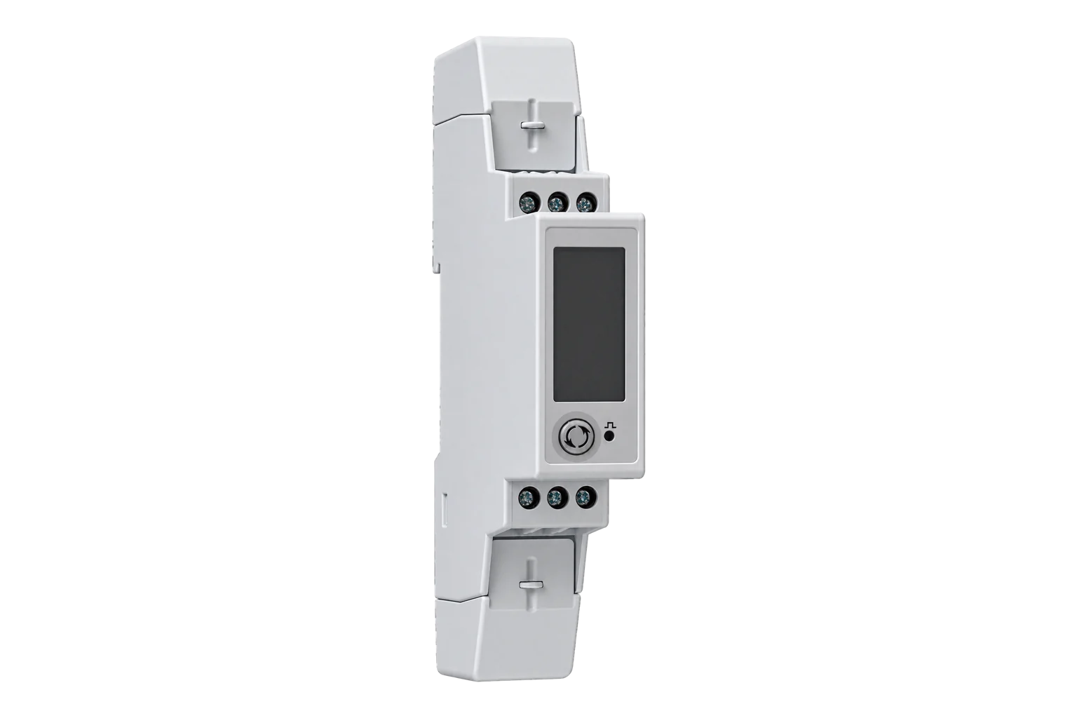
Carlo Gavazzi EM24-DIN
Three-phase energy meter
EM24-DIN combines local energy readout with direct or transformer-operated inputs. The IS option adds RS-485 Modbus. Its measurements use scaled integers with the low word first, so a correct address alone is not enough: verify word order, sign and scale before enabling the rest of the map.

Compatibility
Compatible through Modbus RTU
The manufacturer publishes the measurement register map and communication settings used by an Edge Modbus client.
EM24-DIN PFA, PFB and X models with the IS RS-485 option. M1 M-Bus, DP Dupline and EM24 Ethernet are separate interfaces; the Ethernet map is not interchangeable.
Connect it with
-
Modbus Interface ZMB-3XFrom €399 ex VAT Configure Modbus Interface
-
Gateway ZGW-20From €899 ex VAT Configure Gateway


When the meter is away from the Gateway
- Modbus
- Wireless
- Edge
- Platforms
When an isolated RS-485 interface is available at the Gateway
- Modbus
- Edge
- Platforms
Specifications
The EM24-DIN is a three-phase energy analyser in a 4-module DIN-rail housing, with a joystick and LCD for local readout and set-up. Carlo Gavazzi builds it for active and reactive energy metering and for cost allocation. It measures phase and system voltage, current, active, apparent and reactive power, power factor and frequency, and keeps total and partial kWh and kvarh counters, with up to four tariffs.1
- Active energy accuracy
- Class 1 (EN 62053-21); Class B (EN 50470-3)1
- Reactive energy accuracy
- Class 2 (EN 62053-23)1
- Direct connection (AV2, AV9)
- 10(65) A per phase1
- CT connection (AV5, AV6)
- 1/5(10) A secondary1
- Voltage (AV5)
- 160 to 480 V L-N, 277 to 830 V L-L1
- Systems (standard versions)
- 3-phase 4-wire and 3-wire, 2-phase 3-wire, 1-phase 2-wire1
- Legal metrology
- MID certified with the PF option; only the total imported energy counter is certified1
- Dimensions
- 71 × 90 × 64.5 mm, 4 DIN modules1
- Protection
- IP50 front, IP20 terminals1
- Operating temperature
- -25 to 55 °C, 0 to 90 % RH non-condensing1
- RS-485 settings
- Unit address 1–247; 4800 or 9600 bit/s; match installed parity and stop bits1
- Auxiliary power
- AV2/AV9: measured supply. AV5/AV6: ordering option L 18–60 V AC/DC or D 115/230 V AC1
- Read request size
- Up to 11 registers per request unless the protocol specifies otherwise; up to 500 ms response time2
Interface
This register map is for the EM24-DIN PFA/PFB/X RS-485. AV2 / AV9 with IS, AV5 / AV6 with IS and M1, DP or Ethernet variants have their own interfaces and are not covered here.
Communication settings
- Protocol
- Modbus RTU (JBUS) over RS-485
- Unit address
- 1 to 247
- Baud rate
- 4800 or 9600 bit/s, set on the meter
- Parity and stop bits
- Set on the meter; the instruction manual lists the options
- Registers per request
- Up to 11
- Response time
- 40 ms typical, 500 ms maximum
- Bus termination
- 120 Ω between A and B at both ends of the bus
- Bus loading
- 1/5 unit load; a repeater is needed beyond 160 meters on one bus or 1,000 m of cable
- Read with
- FC04 (FC03 returns the same values)
- Word order
- Low word first on each 32-bit value
- Addresses
- Zero-based PDU addresses, as sent on the bus
From EM24-DIN PFA, PFB & X models - Communication Protocol2.
Register map
| Point | Address | Hex | Format | Scale | Unit |
|---|---|---|---|---|---|
| Voltage L1-N | 0 | 0x0000 |
INT32 | ×0.1 | V |
| Voltage L2-N | 2 | 0x0002 |
INT32 | ×0.1 | V |
| Voltage L3-N | 4 | 0x0004 |
INT32 | ×0.1 | V |
| Voltage L1-L2 | 6 | 0x0006 |
INT32 | ×0.1 | V |
| Voltage L2-L3 | 8 | 0x0008 |
INT32 | ×0.1 | V |
| Voltage L3-L1 | 10 | 0x000A |
INT32 | ×0.1 | V |
| Current L1 | 12 | 0x000C |
INT32 | ×0.001 | A |
| Current L2 | 14 | 0x000E |
INT32 | ×0.001 | A |
| Current L3 | 16 | 0x0010 |
INT32 | ×0.001 | A |
| Active Power L1 | 18 | 0x0012 |
INT32 | ×0.1 | W |
| Active Power L2 | 20 | 0x0014 |
INT32 | ×0.1 | W |
| Active Power L3 | 22 | 0x0016 |
INT32 | ×0.1 | W |
| Apparent Power L1 | 24 | 0x0018 |
INT32 | ×0.1 | VA |
| Apparent Power L2 | 26 | 0x001A |
INT32 | ×0.1 | VA |
| Apparent Power L3 | 28 | 0x001C |
INT32 | ×0.1 | VA |
| Reactive Power L1 | 30 | 0x001E |
INT32 | ×0.1 | VAr |
| Reactive Power L2 | 32 | 0x0020 |
INT32 | ×0.1 | VAr |
| Reactive Power L3 | 34 | 0x0022 |
INT32 | ×0.1 | VAr |
| Average Voltage L-N | 36 | 0x0024 |
INT32 | ×0.1 | V |
| Average Voltage L-L | 38 | 0x0026 |
INT32 | ×0.1 | V |
| Total Active Power | 40 | 0x0028 |
INT32 | ×0.1 | W |
| Total Apparent Power | 42 | 0x002A |
INT32 | ×0.1 | VA |
| Total Reactive Power | 44 | 0x002C |
INT32 | ×0.1 | VAr |
| Power Factor L1 | 50 | 0x0032 |
INT16 | ×0.001 | - |
| Power Factor L2 | 51 | 0x0033 |
INT16 | ×0.001 | - |
| Power Factor L3 | 52 | 0x0034 |
INT16 | ×0.001 | - |
| Total Power Factor | 53 | 0x0035 |
INT16 | ×0.001 | - |
| Frequency | 55 | 0x0037 |
INT16 | ×0.1 | Hz |
| Import Active Energy | 62 | 0x003E |
INT32 | ×0.1 | kWh |
| Import Reactive Energy | 64 | 0x0040 |
INT32 | ×0.1 | kVArh |
| Export Active Energy | 92 | 0x005C |
INT32 | ×0.1 | kWh |
| Export Reactive Energy | 94 | 0x005E |
INT32 | ×0.1 | kVArh |
Assessment
EM24-DIN PFA, PFB and X models with the IS RS-485 option. M1 M-Bus, DP Dupline and EM24 Ethernet are separate interfaces; the Ethernet map is not interchangeable.
- InteroperabilityWell supported
- A published serial map specifies both read functions, physical addresses, signed formats, word order and scaling.2
- AccuracySupported with conditions
- The datasheet defines direct and CT inputs plus Class 1 active and Class 2 reactive energy. Certified imported energy is limited to the PF option.1
- SecurityNot yet assessed
- The reviewed documents do not establish authenticated or encrypted register access. Network security requires a separate installation review.2
- ReliabilitySupported with conditions
- Maximum response time, request limits and explicit overflow behaviour are documented and can be handled by the reader.2
- RuggednessSupported with conditions
- IP50 front, IP20 terminals and -25 to +55 °C define an enclosed DIN-rail installation.1
Edge template
This JSON file supplies the register map. Applying it to an existing meter replaces its sensor list while retaining the site connection, unit ID and enable state.
| Model | Connection | Points | Version | Updated | Download |
|---|---|---|---|---|---|
| EM24-DIN PFA/PFB/X RS-485 | Modbus RTU (JBUS) over RS-485 | 32 | 1.0.0 | Download |
Downloads need a signed-in account with Edge download access.
Use the template in Edge
- Import the JSON file
In Edge, open Settings, then Devices and Templates. Choose Import JSON and select the downloaded file. Confirm that the model and template name match your device.
- Load the map for your meter
For a new Modbus device, use Load Template before entering the manufacturer or model; it fills those fields and the register list. Set the name, site connection and unit ID, check the polling enable state, then test before saving. For an existing device, apply only to the matching model; this replaces its sensor list but retains its connection, unit ID and enable state.
- Test a reading
Use Test in the wizard and compare a known reading with the meter display. Check its unit, sign and scale, then confirm that timestamps keep advancing. These starter maps are read-only and leave exports off until you configure them.
Setup
Read L1-N voltage as a scaled integer
Use the physical address column in the EM24-DIN PFA/PFB/X communication protocol, version 4 revision 0.
- Function
- FC04 Read Input Registers; FC03 returns the same measurement values
- PDU start
- 0 (0x0000), two registers
- Format
- Signed INT32; least significant word first, high byte first inside each word
- Scale
- 0.1 V per count; no additional CT multiplier on voltage
- Independent vector
- A simulated 230.0 V value is raw 2300 = 0x000008FC. Returned words 0x08FC, 0x0000 become bytes 08 FC 00 00.
- Request PDU
- 04 00 00 00 02; the Modbus client adds the actual unit address and CRC
- Invalid value
- A high word of 0x7FFF indicates overflow and must not be treated as measured voltage
Acceptance: The vector tests decoding only. Compare several fresh readings with the meter display, then repeat with current and signed power. A swapped-word integer can still look plausible at one operating point.
-
Read the complete order code
Confirm IS RS-485 and the input range: AV2/AV9 direct connection or AV5/AV6 CT secondary. Record the installed CT ratio and auxiliary supply where applicable. Do not treat an Ethernet EM24 as the same register map.
-
Connect one serial master
Use a two-wire RS-485 bus with the documented reference and end termination. Match the unit address, 4800 or 9600 bit/s and the installed parity/stop settings. Resolve ownership of an existing bus before adding a reader.
-
Verify one scaled integer
Read voltage L1-N at PDU address 0 with FC04 and two registers. Decode signed INT32, low word first, high byte first within each word, then multiply by 0.1 V. Compare fresh values with the display on a wiring mode that provides L1-N.
-
Import the existing Edge template
Download and import the 32-point EM24-DIN RS-485 core template. Keep requests within the documented 11-register limit. Check current and signed total power against the local display before enabling every point.
-
Handle invalid readings and counters
The protocol flags overflow with 0x7FFF in the high word. Do not export that as a numeric reading. Preserve communications failure and stale states separately from zero. This read-only setup does not reset energy or change CT ratios.
Common questions
- Which EM24-DIN models have Modbus?
- Models with the IS option in the order code have an RS-485 port that speaks Modbus RTU, plus three digital inputs. The M1 option is M-Bus and the DP option is Dupline, and neither speaks Modbus.1
- Are the EM24 register addresses zero-based?
- Yes. The addresses on this page are the protocol document’s hexadecimal addresses used as zero-based PDU addresses, so Voltage L1-N is input register 0. A master that uses 30001-style numbering shows it as 30001.2
- How are 32-bit values ordered?
- Carlo Gavazzi sends the least significant word first, with the most significant byte first inside each word. In Edge that is big-endian bytes with word swap on every INT32 register.2
- Can the EM24-DIN be used for billing?
- The datasheet identifies the PF option as MID certified and limits the certified quantity to total imported active energy. Exported energy and the other measurements are outside that stated certification; verify the installed order code and meter markings.1
Related devices


Sources
- EM24 DIN three-phase energy analyzer datasheet (DS 260315) (opens in a new tab) (PDF)
- EM24-DIN PFA, PFB & X models - Communication Protocol (opens in a new tab) (PDF)
Further reading
- ApplicationBMS and SCADA meter integration
- ToolModbus data decoder
- ToolModbus register address translator
- GuideModbus commissioning over RS-485
- ToolRS-485 termination and bias
- ComparisonCompare three direct-connected Modbus meters
- ManufacturerCarlo Gavazzi devices
- ProtocolModbus devices and register maps
- CategoryEnergy meters
Product names and trademarks belong to their owners. Publication does not imply endorsement or a commercial relationship.