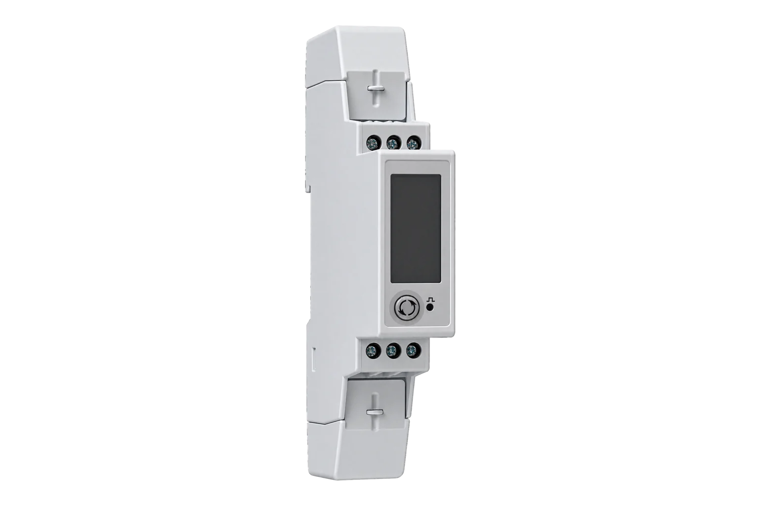
Carlo Gavazzi EM111 S1
Power and energy meter
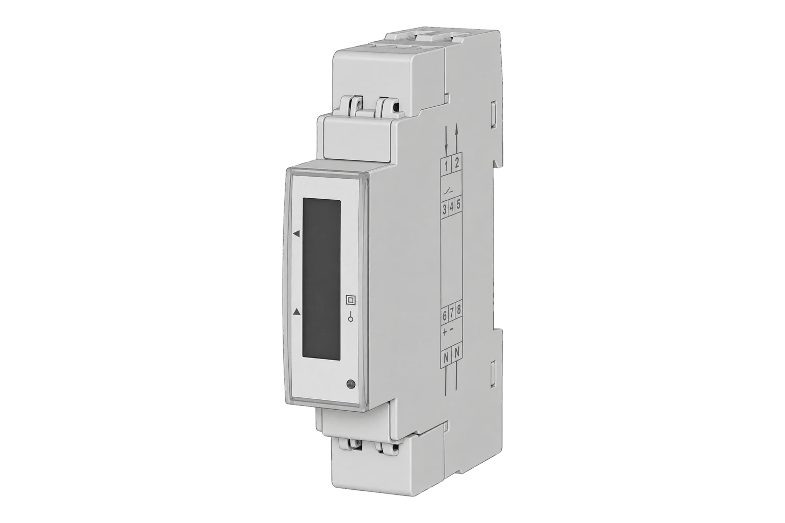
EM111DINAV81XS1X is the non-MID, single-phase 230 V variant with RS-485 Modbus RTU. Its protocol distinguishes six-digit Modicon references from physical addresses: L1-N voltage begins at physical 0x0000 and is a two-register INT32 in tenths of a volt. The product page’s 5(45) A shorthand must be read alongside the installation and data-sheet limit for the actual conductor.
- Modbus RTU
Power and energy meter
Compatibility
Documented read-only Modbus path
The manufacturer documents Modbus RTU on the exact S1 order and a read-only physical-address map.
Exact EM111DINAV81XS1X (AV8, single-phase two-wire, self-powered, RS-485 S1, non-MID X), with the retained EM111 datasheet and EM100/ET100 protocol revision 14. The product page gives 5(45) A while its specification and datasheet say direct connection up to 32 A without the stated larger conductor condition. Use the installation-specific terminal and conductor rating; this guide does not approve 45 A wiring. MID PFA/PFB, M-Bus and CT-input variants are separate.
Connect it with
-
Modbus Interface ZMB-3XFrom €399 ex VAT Configure Modbus Interface
-
Gateway ZGW-20From €899 ex VAT Configure Gateway


For the documented RS-485 Modbus RTU server interface
- Modbus
- Edge
- Platforms
Models
| Models | Interface | Route into Edge |
|---|---|---|
| EM111DINAV81XS1X | RS-485 Modbus RTU; direct AV8 current input | Read documented measurements on the serial path. |
| EM111 M1, O1, AV5 and PFA/PFB orders | M-Bus, pulse, CT input or MID options differ | Do not infer this exact hardware identity or legal metrology status from a family name. |
Interface
Documented measurements and integration boundaries for EM111 S1.
- L1-N voltage at physical address 0x0000, INT32 in 0.1 V.
- Current at physical 0x0002, INT32 in 0.001 A.
- Active power at physical 0x0004, INT32 in 0.1 W.
- Import energy and tariff counters with their own width, mode and scaling.
Assessment
Exact EM111DINAV81XS1X (AV8, single-phase two-wire, self-powered, RS-485 S1, non-MID X), with the retained EM111 datasheet and EM100/ET100 protocol revision 14. The product page gives 5(45) A while its specification and datasheet say direct connection up to 32 A without the stated larger conductor condition. Use the installation-specific terminal and conductor rating; this guide does not approve 45 A wiring. MID PFA/PFB, M-Bus and CT-input variants are separate.
- InteroperabilityWell supported
- The exact S1 order is Modbus RTU and the manufacturer defines FC03/FC04, physical addresses and low-word-first INT32 layout.13
- AccuracySupported with conditions
- The exact AV8 order is a direct-connected single-phase meter; current installation limits and measurement direction must be checked.12
- SecurityNot yet assessed
- The retained protocol does not establish authentication or encrypted serial transport.3
- ReliabilitySupported with conditions
- The protocol defines illegal-address and overflow behaviour; invalid or impossible samples require explicit rejection.3
- RuggednessSupported with conditions
- The datasheet gives installation and environmental limits; verify the enclosure and conductor sizing.2
- ScalabilitySupported with conditions
- Modbus unit addresses 1–247 are supported, but bus capacity depends on the serial wiring and poll schedule.3
Setup
Decode a voltage read with the documented word order
Revision 14 maps L1-N voltage to physical 0x0000 as two-register signed INT32, weighted at 0.1 V.
- Request PDU
- 03 00 00 00 02: FC03, physical address 0x0000, two registers.
- Synthetic response data
- 08 FC 00 00: low word 0x08FC followed by high word 0x0000.
- Decode
- 0x000008FC = 2300 signed; 2300 × 0.1 V = 230.0 V. Bytes within each word are high byte first.
- Acceptance
- Reject overflow and compare the fresh result with the simultaneous display on the same circuit.
Acceptance: The bytes are a synthetic independent decoder check, not a captured meter reply. A real response must match the installed order and display before other points are enabled.
-
Read the full EM111DINAV81XS1X order code and confirm AV8 direct input, S1 serial port and non-MID X option.
Have the installer apply the datasheet’s conductor-dependent current limit.
-
Confirm the device address and actual serial framing before bus collection.
Avoid a shared factory address when several meters are installed.
-
For a first read, send FC03 or FC04 to physical address 0x0000 for two registers.
Do not send Modicon 300001 as the PDU address.
-
Decode each register high byte first, combine the INT32 low word before high word, then divide the raw signed value by ten for V.
Reject overflow markers and compare with the meter display.
-
Check the measurement mode before interpreting import and export energy; do not assume a total counter equals imported consumption in every configuration.
Common questions
- Why is the wire address zero when the table says 300001?
- The protocol calls 300001 a six-digit Modicon reference and separately prints physical address 0000h, which is the word address sent in the frame.3
- Can the order be used for MID billing?
- The X option is the non-MID version in the retained datasheet. PFA/PFB are distinct certified variants, and installation requirements still matter.12
- Is 45 A always allowed?
- No. The datasheet states direct connection up to 32 A and separately describes a 45 A maximum subject to a conductor condition. Use the exact installation instructions and terminal rating.2
Related devices



Sources
- EM111DINAV81XS1X exact product page (opens in a new tab)
- EM111 datasheet revision 310826, order and current limits (opens in a new tab) (PDF)
- EM100 and ET100 series Modbus protocol version 2 revision 14 (opens in a new tab) (PDF)
Further reading
Product names and trademarks belong to their owners. Publication does not imply endorsement or a commercial relationship.