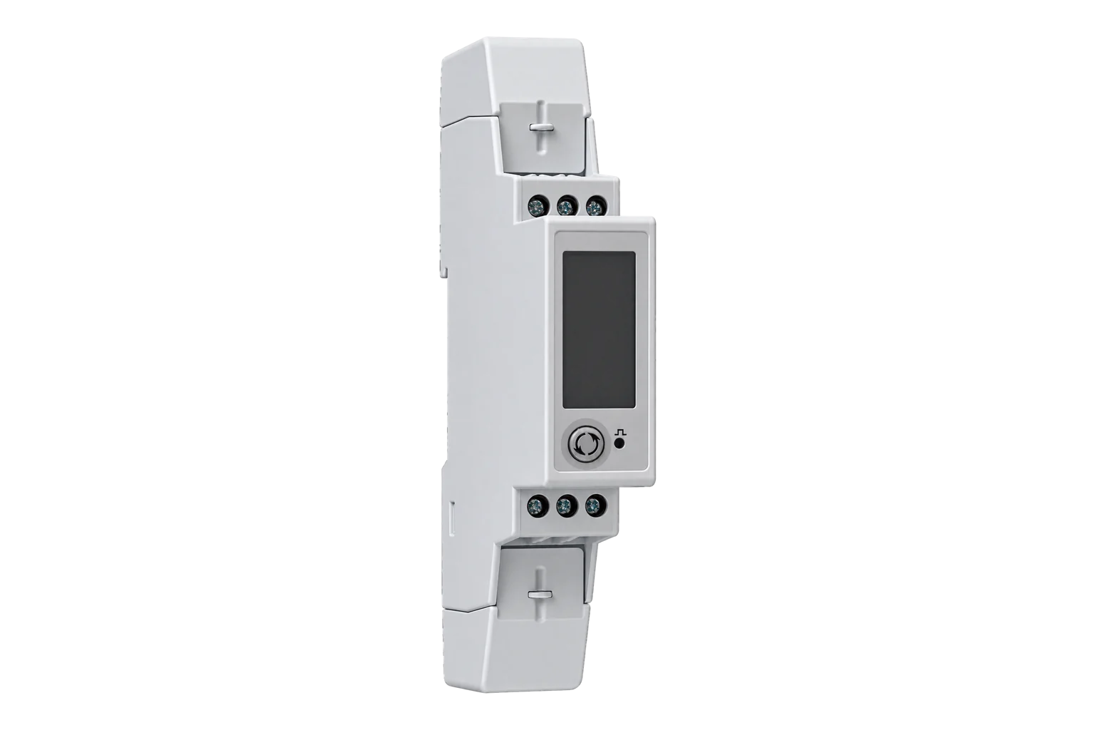
Carlo Gavazzi EM340 S1 X
Power and energy meter
EM340DINAV23XS1X measures a circuit directly up to 65 A, with 208–400 V line-to-line inputs and self power supply. The S1 option provides Modbus RTU; the final X is the standard, non-MID option. This is distinct from CT-input EM330, M-Bus M1 and pulse-output O1 variants. Select bidirectional measurement when separate import and export energy are needed.
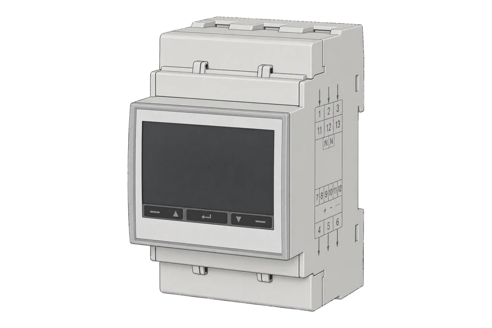
- Modbus RTU
Power and energy meter
Compatibility
Compatible through Modbus RTU
The manufacturer documents RS-485 Modbus RTU reads with physical addresses, integer scaling and low-word-first ordering.
EM340DINAV23XS1X with AV2 direct input and S1 RS-485. Use the version 2 revision 17 map as a best-effort starting point, read two complete words and compare the display. Record the serial number: the July 2026 datasheet identifies updated units from 2026150000A with larger read blocks. Keep monitoring read-only and reject overflow before scaling.
Connect it with
-
Modbus Interface ZMB-3XFrom €399 ex VAT Configure Modbus Interface
-
Gateway ZGW-20From €899 ex VAT Configure Gateway


For the exact RS-485 order code described here
- Modbus
- Wireless
- Edge
- Platforms
Models
| Models | Interface | Route into Edge |
|---|---|---|
| EM340 DIN AV2 3 X S1 X | Direct 5(65) A, self powered, RS-485 Modbus RTU; non-MID | Exact scope of this read-only guide. |
| EM330 S1 | CT-input family; its ratio configuration is not the EM340 direct-input installation | Shared protocol document does not make the electrical inputs interchangeable. |
| EM340 O1 / M1 / PF | Pulse, M-Bus or certified-option variants | Check the complete order code. S1 identifies the RS-485 route; X does not inherit PF certification. |
| EM340 produced from June 2026 | Updated hardware identified from serial 2026150000A | Use the current datasheet and Annex A for generation-dependent limits; retain the installed firmware record. |
Specifications
For a circuit within its direct connection current rating, EM340 avoids external CT selection and ratios. The full order code matters: AV2 fixes the input range, S1 supplies RS-485, and the final X is not the MID option. The 2026 datasheet also distinguishes new production from older meters under the same model name.24
- Exact order
- EM340DINAV23XS1X: AV2 input, three-phase system, self powered, S1 RS-485, standard X option.4
- Electrical input
- Direct 5(65) A; nominal 120–230 V L-N / 208–400 V L-L. No external CT input on this version.4
- Wiring systems
- Three-phase three- or four-wire and two-phase three-wire configurations listed for the X option.2
- Energy
- Import/export active and reactive energy; class 1 active energy. The X option is explicitly not MID certified.2
- Serial interface
- Modbus RTU on RS-485; address 1–247; configurable speed, parity and stop bits. One-second data refresh.2
- Generation boundary
- Serial 2026150000A begins the June 2026 update. Read-command limit: 125 words for updated units, 50 for earlier units; this guide reads only two.2
- Mounting and protection
- Three DIN modules, 54 × 90 × 63 mm; front IP51, terminals IP20; X-option operation −25 to +65 °C indoors under the stated humidity limit.2
Interface
Documented measurements and integration boundaries for EM340 S1 X.
- Phase-neutral voltage starts at physical address 0x0000: two 16-bit registers forming a signed 32-bit value, scale 0.1 V, low word first.
- Phase current at 0x000C uses 0.001 A, while active power at 0x0012 uses 0.1 W. Do not reuse one multiplier for all quantities.
- The grouped map provides separate total import and export energy. Measurement mode A combines direction; mode B preserves bidirectional behaviour.
- Overflow code 0x7FFFFFFF arrives as words FFFF 7FFF. Reject it before applying the multiplier.
- The protocol also documents higher-resolution energy totalizers; select the corresponding address, width and resolution instead of changing the multiplier on the older counter.
Assessment
Exact EM340DINAV23XS1X, AV2 direct input and S1 RS-485. The current product page links protocol version 2 revision 17 (2021); this is a document revision, not the installed firmware. Record firmware and serial number. The July 2026 datasheet identifies updated units from serial 2026150000A and changes the read-command limit from 50 to 125 words. The two-register example avoids that boundary and the older protocol’s inconsistent 20/50-word descriptions. No physical validation or automatic template is claimed; reject the finite overflow marker before scaling.
- InteroperabilityWell supported
- The exact product links a protocol defining physical addresses, FC03/04, signed data, word order and scaling.14
- AccuracySupported with conditions
- Direct 65 A input and stated accuracy fit bounded circuits; measurement mode determines directional energy meaning.12
- SecurityNot yet assessed
- The reviewed documents do not establish authenticated or encrypted Modbus access for this exact meter.1
- ReliabilitySupported with conditions
- Overflow indication and energy-storage behaviour are documented; reject overflow and verify totals after commissioning.12
- RuggednessSupported with conditions
- Indoor DIN mounting, IP51 front/IP20 terminals and X-option temperature limits define the installation envelope.2
Setup
Read L1-N voltage without reversing the bytes inside words
The current product links the manufacturer’s version 2 revision 17 protocol. Its physical address and two-word INT32 format support this bounded read.
- Function
- FC03 Read Holding Registers; FC04 has the same documented effect
- Address
- Physical 0x0000 = 0 decimal; printed Modicon reference 300001
- Quantity
- 2 registers, 4 data bytes
- Request PDU
- 03 00 00 00 02
- Synthetic response data
- 08 FC 00 00: low word 0x08FC, then high word 0x0000
- Decode
- Signed integer 2300 ÷ 10 = 230.0 V
- Invalid value
- FFFF 7FFF is 0x7FFFFFFF overflow; reject before scaling
Acceptance: This synthetic vector is independently calculated, not a physical meter capture. Swap the two 16-bit words for numeric assembly, while retaining high-byte-first order within each word. Verify the result against the actual display.
-
Confirm the complete code and production generation
Record EM340DINAV23XS1X, serial number and firmware. The current datasheet distinguishes updated units from serial 2026150000A. Confirm the actual direct-connected circuit is within the AV2 voltage and 65 A input limits; EM330 CT settings do not belong to this model.
-
Choose the energy meaning before reading totals
Check the wiring-system setting and measurement selection. For the X option, mode A treats power direction as positive; mode B provides bidirectional import/export behaviour. Select the intended mode through the authorised commissioning process, then retain it with the point-list documentation.
-
Match serial settings and termination
Read the configured Modbus address, speed, parity and stop bits from the meter and match them in Edge. Follow the manufacturer’s RS-485 wiring. The protocol uses terminal T to terminate the final instrument; do not apply termination at every meter.
-
Read two words at physical address zero
For L1-N voltage, send FC03 or FC04 to physical address 0x0000 with quantity 2. The printed reference 300001 is not the PDU address. Decode signed INT32 with low word first and high byte first inside each word, then divide by 10.
-
Reject overflow and compare before expanding
Treat raw 0x7FFFFFFF as overflow, not an enormous valid voltage. Compare the decoded result with the meter display. Add current, power and energy with their own map rows, and compare an energy delta. Keep resets and configuration writes outside this monitoring path.
Common questions
- Is EM340 a CT-input meter?
- No. The AV2 EM340 specified here measures the load directly up to 65 A. EM330 is the CT-input sibling in the shared protocol document. A common register layout is not permission to connect external CTs to the EM340 current path.2
- Why is export energy not behaving as expected?
- The X option supports measurement selection A or B. Mode A integrates power without direction, while B provides bidirectional behaviour. Check that selection and the actual wiring before interpreting separate imported and exported totals.1
- Should I enter 300001 as the start address?
- No. The table’s physical address is the value included in the request: 0x0000 for L1-N voltage. Its six-digit Modicon reference names the input-register convention. Both FC03 and FC04 are documented for the same measurements.1
- Can every EM340 read 125 registers at once?
- No. The July 2026 datasheet gives 125 words for updated production, while Annex A gives 50 words for earlier units. The older protocol also has inconsistent 20/50-word limit text. The two-word check stays below every stated limit; qualify larger reads against the actual generation.2
- Why is no ready-made template offered on this exact guide?
- The overflow code is a finite signed integer, so a normal numeric decoder would turn it into a misleading measurement. A prepared import needs explicit sentinel handling and exact-generation qualification. The broader family download is not physical validation of this exact unit.1
Related devices



Sources
- EM300/ET300 communication protocol, version 2 revision 17, 5 July 2021 (opens in a new tab) (PDF)
- EM340 datasheet DS 070726, including June 2026 change annex (opens in a new tab) (PDF)
- EM340 installation instructions (opens in a new tab) (PDF)
- EM340DINAV23XS1X exact product specification (opens in a new tab)
Further reading
- ToolModbus register address translator
- ToolModbus register decoder
- GuideEM330/EM340 family register overview
- GuideEM530/EM540 S1: newer CT and direct-input options
- ToolRS-485 termination and bias
- GuideModbus RS-485 commissioning
- ManufacturerCarlo Gavazzi devices
- ProtocolModbus devices and register maps
- CategoryEnergy meters
Product names and trademarks belong to their owners. Publication does not imply endorsement or a commercial relationship.