Carlo Gavazzi EM210
Three-phase energy meter
The EM210 is a three-phase energy analyser that measures through external current transformers and fits either a DIN rail or a 72 x 72 mm panel cut-out, thanks to its detachable display. Orders with S in the output 2 position add a 2-wire RS-485 port running Modbus RTU. Carlo Gavazzi's protocol gives every measurement a physical word address, a scale factor and a data type: most values are signed 32-bit integers sent low word first, so voltage at 0x0000 arrives in tenths of a volt with the low word in the first register.

Compatibility
Compatible with EpiSensor Edge over Modbus RTU
Carlo Gavazzi documents Modbus RTU on the EM210's optional RS-485 port and publishes a register map with physical addresses, data types, word order and scaling. This is documented compatibility, without a physical Edge test.
EM210 orders with S in the output 2 position (RS-485 port), using the EM210_AV communication protocol version 4 revision 3 as a best-effort starting point. The AV5 and AV6 current-transformer models match that document directly; on MV5 and MV6 models compare the first reads with the display. Orders with X in the output 2 position have no RS-485 port. THD, neutral current and hour counters need firmware A.5 or later. Read-only monitoring.
Connect it with
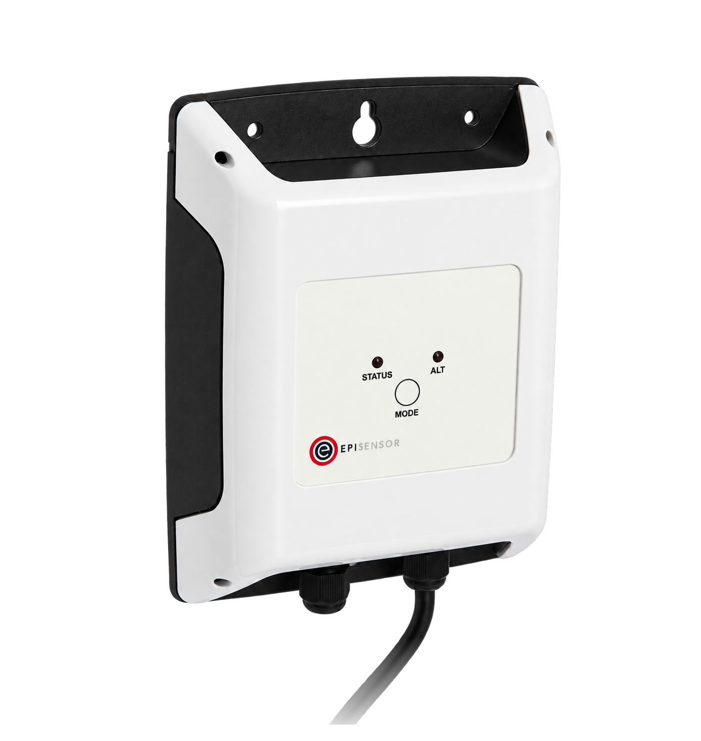
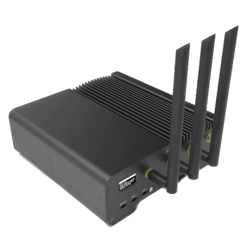
For an EM210 with the S option (RS-485 port on terminals 15 to 18)
- Modbus
- Edge
- Platforms
Models
| Models | Interface | Route into Edge |
|---|---|---|
| EM210 72D AV5 3 X O S X and AV6 3 X O S X | 5(6) A current-transformer inputs (AV5 240/415 V, AV6 133/230 V with VT/PT); RS-485 Modbus RTU on terminals 15 to 18; one static pulse output on 12 and 13 | Read the protocol's measurement tables with FC03 or FC04 on the serial path. Set the CT and VT ratios on the meter, not from Edge. |
| EM210 72D MV5 3 X O S X and MV6 3 X O S X | 0.333 V current sensors (CTV series) or ROG4X/ROG4U Rogowski coils; the same RS-485 port | Same read path. The retained protocol is titled EM210_AV and does not list the MV sensor-type and primary-current settings, so compare voltage, current and power with the display before adding points. |
| EM210 orders ending O X X | Static pulse output only; X in the output 2 position means no RS-485 port | No Modbus path. This register map does not apply. |
Specifications
The EM210 is a general-purpose three-phase energy meter for active and reactive energy and the main electrical quantities. It measures through external current transformers or current sensors only, takes its supply from the measured voltage, and has a removable LCD display that converts the same unit from a 4-module DIN-rail meter to a 72 x 72 mm panel meter. A static pulse output is standard; the RS-485 port is an ordering option.23
- Order code
- EM210 72D, then range AV5, AV6, MV5 or MV6, system 3, supply X (self-powered), output 1 O (static pulse), output 2 X (none) or S (RS-485 port), option X.2
- Measuring inputs
- AV5: 240/415 V AC, 5(6) A CT input. AV6: 133/230 V AC with VT/PT and CT connection. MV5 and MV6: the same voltages with 0.333 V CTV current sensors or ROG4X/ROG4U Rogowski coils. Every model needs external current transformers or sensors.2
- Systems
- 3-phase 4-wire, 3-phase 3-wire (including two-CT ARON on AV5 and AV6), 3-phase balanced with one CT, 2-phase 3-wire and 1-phase 2-wire.23
- Accuracy
- Active energy class 1 (EN 62053-21); reactive energy class 2 (EN 62053-23); current and phase-neutral voltage +/-(0.5% RDG + 1 DGT) over most of the range; frequency resolution 1 Hz.2
- RS-485
- Modbus RTU on terminals 15 (A-), 16 (B+), 17 (GND) and 18 (T). Addresses 1 to 247; 9.6, 19.2, 38.4, 57.6 or 115.2 kbit/s. The protocol gives 9600 bit/s, no parity and 1 stop bit as defaults, with even parity or 2 stop bits selectable.12
- Bus
- 1/5 unit load: up to 160 instruments and 1000 m before a repeater is needed. Terminate the last meter by linking B+ and T.13
- Pulse output
- One opto-mosfet output on terminals 12 and 13, programmable from 0.01 to 9.99 kWh per pulse, 30 or 100 ms pulse width.23
- Approvals
- CE, UKCA and cULus listed; safety EN 61010-1; metrology EN 62053-21 and EN 62053-23.2
- Housing
- 4 DIN modules or 72 x 72 mm panel mounting; 72 x 72 x 65 mm. Front IP40, screw terminals IP20.2
Interface
Documented measurements and integration boundaries for EM210.
- Addresses are physical word addresses sent in the frame: L1-N voltage is printed as Modicon 300001 and physical 0000h, and goes on the wire as 0x0000. FC03 and FC04 return the same values.
- INT32 values are two registers, low word first, with each word high byte first. Signed values use two's complement.
- L1-N, L2-N and L3-N voltage at 0x0000, 0x0002 and 0x0004; L1-L2, L2-L3 and L3-L1 at 0x0006, 0x0008 and 0x000A: INT32, volts x 10.
- L1, L2 and L3 current at 0x000C, 0x000E and 0x0010: INT32, amperes x 1000. Neutral current (calculated) at 0x0098, same scale, firmware A.5 or later.
- L1 to L3 active power at 0x0012 to 0x0016 (W x 10), apparent power at 0x0018 to 0x001C (VA x 10) and reactive power at 0x001E to 0x0022 (var x 10): INT32.
- System values: V L-N at 0x0024 and V L-L at 0x0026 (V x 10), W at 0x0028, VA at 0x002A and var at 0x002C (x 10): INT32.
- Power factor L1, L2, L3 and system at 0x002E to 0x0031: one register each, INT16, PF x 1000. A negative value means exported active power.
- Phase sequence at 0x0032 (INT16: -1 is L1-L3-L2, 0 is L1-L2-L3) and frequency at 0x0033 (INT16, whole hertz).
- Total active energy kWh(+) at 0x0034, reactive energy kvarh(+) at 0x0036 and exported active energy kWh(-) at 0x004E: INT32, kWh x 10 and kvarh x 10. Whether kWh(+) is import only depends on the application setting.
- Hour counters at 0x005A (kWh+) and 0x005C (kWh-): INT32, hours x 100. Per-phase voltage and current THD at 0x0082 to 0x0096 (% x 100) when THD is enabled; the two system THD words read 0.
- Identity: Carlo Gavazzi identification code at 0x000B (UINT16, 210 for the standard EM210), firmware version and revision at 0x0302 and 0x0303, programming lock at 0x0304, serial number as ASCII at 0x5000 to 0x5006 and production year at 0x5007. The protocol limits the identification, firmware and lock words to one register per request.
- A second copy of the measurements grouped by phase starts at 0x00F6 (Table 2.4-1). Configuration, serial-port settings and the meter reset at 0x1000 to 0x4000 are writable; keep them out of a monitoring poll.
Assessment
EM210 orders with S in the output 2 position (RS-485 port), using the EM210_AV communication protocol version 4 revision 3 as a best-effort starting point. The AV5 and AV6 current-transformer models match that document directly; on MV5 and MV6 models compare the first reads with the display. Orders with X in the output 2 position have no RS-485 port. THD, neutral current and hour counters need firmware A.5 or later. Read-only monitoring.
- InteroperabilityWell supported
- Carlo Gavazzi documents Modbus RTU on the S option and publishes FC03/FC04, physical and Modicon addresses, register lengths, data types, low-word-first word order and scale factors for every measurement.12
- AccuracySupported with conditions
- Class 1 active and class 2 reactive energy with per-phase voltage, current, power and power factor. Readings depend on correctly set CT and VT ratios, and the application setting decides whether current direction is respected and whether exported energy is counted.12
- SecurityNot yet assessed
- A 0 to 999 password and a rear trimmer lock protect programming, and the lock state is readable at 0x0304, but configuration and reset registers are writable over the RS-485 port.12
- ReliabilitySupported with conditions
- The protocol defines exception codes, a 500 ms maximum and 40 ms typical reply time, a repeat-then-fail rule for missing replies and an overflow marker (most significant word 7FFFh, shown as EEE). Treat failed reads and overflow values as missing data.13
- RuggednessSupported with conditions
- Rated -25 to +55 °C operating, IP40 front and IP20 terminals, overvoltage category III, with 4 kV insulation between the measuring inputs and the communication port. Indoor use inside a suitable enclosure.23
Setup
Read L1-N voltage from physical address 0x0000
EM210_AV communication protocol version 4 revision 3, Table 2.3-1, lists V L1-N at Modicon address 300001, physical address 0000h, two words, INT32, value weight Volt*10. Use that map as the starting point and compare the result with the display.
- Request
- 01 04 00 00 00 02 71 CB: Modbus address 1, FC04, physical address 0x0000, two registers, RTU CRC. FC03 gives the same value: 01 03 00 00 00 02 C4 0B.
- Address convention
- Send the physical address as printed: 0x0000 is the zero-based PDU address 0. A client that numbers registers from one shows it as input register 1 (300001) for FC04 or holding register 1 (400001) for FC03. Do not send 300001, or 1, as the PDU address.
- Synthetic response
- 01 04 04 08 FC 00 00 39 D4: four data bytes, low word 08 FC first, then high word 00 00.
- Decode
- INT32 with the low word first and each word high byte first: 0x000008FC = 2300. The weight is Volt*10, so 2300 / 10 = 230.0 V. A client that takes the high word first reads 0x08FC0000 = 150,732,800, which would show as 15,073,280.0 V.
- Acceptance
- Keep the point when it agrees with L1 voltage on the meter display at the same time; the phase voltage page is shown in applications C to F. If it does not, check the address, word order and order code before adding more points.
Acceptance: The response bytes are a synthetic decoder check, not a captured meter reply. A real reply must agree with the display before current, power and energy points are enabled.
-
Identify the meter
Read the order code on the label. The RS-485 port is present only when the output 2 position is S. Note whether the range is AV5, AV6, MV5 or MV6, and read the firmware release from the information pages on the display.
-
Read the serial and measurement settings
The information menu shows the Modbus address, parity, baud rate and stop bits, the system type and the CT and VT ratios without a password. Enter the same serial values in the Edge serial client and leave the meter's settings as they are.
-
Wire the RS-485 pair
Connect A- to terminal 15, B+ to 16 and the common to GND on 17. Give each meter on the bus its own address and link B+ to T (terminal 18) on the last meter only.
-
Make two reads
Read the identification code at 0x000B, one register, and expect 210. Then read L1-N voltage at 0x0000 for two registers and decode it low word first, as in the worked read below. Compare the result with L1 voltage on the display.
-
Add the points you need
Add current, power and energy from the same table. Check the meter's application setting before relying on export energy, and keep FC06 writes out of the polling configuration.
Common questions
- Why does voltage read as millions of volts?
- The client is taking the high word first. The EM210 sends INT32, UINT32 and UINT64 values with the least significant word first, and each word high byte first. Swap the two registers, then apply the scale: 2300 at 0x0000 is 230.0 V.1
- Should I use FC03 or FC04?
- Either. The protocol says the two functions have exactly the same effect. Its Modicon addresses start with 3 for FC04, and you replace the 3 with a 4 for FC03, but the address in the frame is always the physical address, starting at 0x0000.1
- Why does exported energy stay at zero?
- The application setting decides it. In applications A, B, C and F current, power and energy are measured regardless of current direction, and only application E keeps the exported kWh(-) counter. The protocol gives C as the default. Check APPLiC on the meter, and have the installer change it on the meter if export must be counted separately.12
- Which EM210 has Modbus?
- The order code's output 2 position shows it: S is the RS-485 port with Modbus RTU, X is none. Every EM210 has the static pulse output, but a meter without S has no Modbus port.23
- Are THD and neutral current available on every meter?
- No. The protocol added THD, calculated neutral current and the hour counters for firmware revision A.5, and the wrong-connection status for A.6. THD needs the THD function enabled, the two system THD words always read 0, and the datasheet lists neutral current only for 3-phase 4-wire unbalanced and 2-phase systems. Read the firmware version at 0x0302 and 0x0303 first.12
Related devices
Sources
- EM210_AV communication protocol, version 4 revision 3 (10 May 2018) (opens in a new tab) (PDF)
- EM210 energy analyzer datasheet (EM210 DS 160922), order code and specifications (opens in a new tab) (PDF)
- EM210 installation and use instructions (8021854, 2018-11, with the 8021895 2019-02 Chinese edition) (opens in a new tab) (PDF)
Further reading
- ToolModbus register address translator
- ToolModbus data decoder
- GuideModbus commissioning over RS-485
- GuideEM24-DIN RS-485: the same low-word-first INT32 format
- GuideEM530/EM540 S1: newer CT and direct-input options
- ToolRS-485 termination and bias
- ManufacturerCarlo Gavazzi devices
- ProtocolModbus devices and register maps
- CategoryEnergy meters
Product names and trademarks belong to their owners. Publication does not imply endorsement or a commercial relationship.