Carlo Gavazzi EM270 / EM280
Power and energy meter
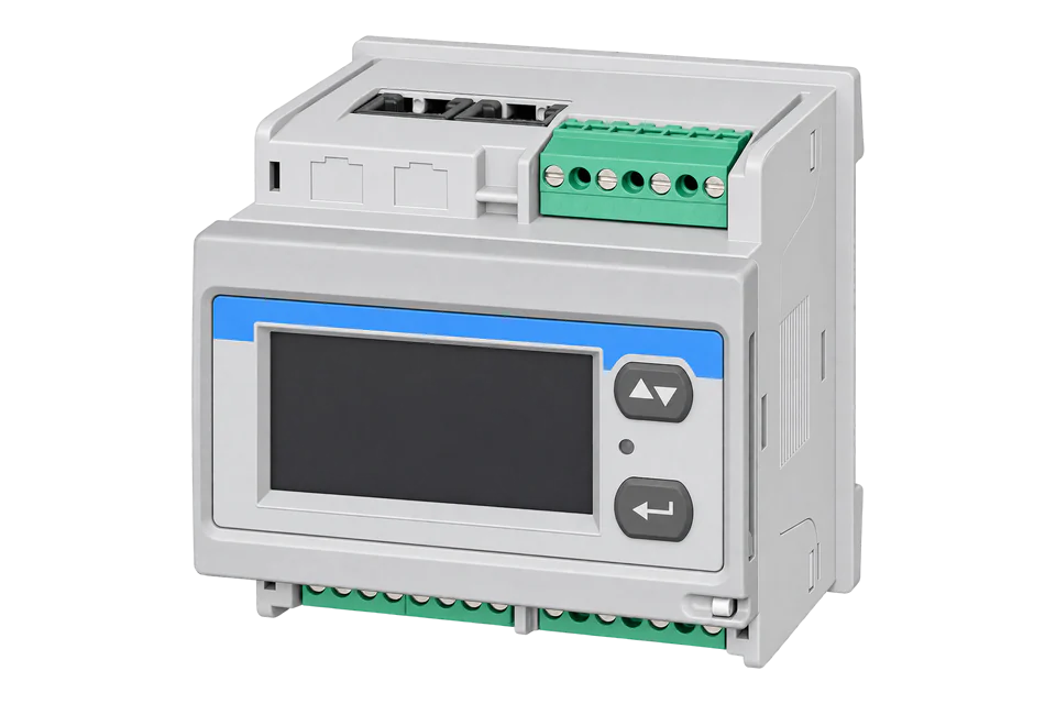
The EM270 and EM280 are self-powered, DIN-rail or 72 x 72 mm panel analysers that measure up to two three-phase circuits or six single-phase circuits from one voltage reference. The EM270 takes solid-core TCD blocks from 65 A to 630 A; the EM280 takes the 6-channel TCD06BS (split core) or TCD06BX (solid core) block at 32 A. Both answer Modbus RTU on a 2-wire RS-485 port, and Carlo Gavazzi publishes one communication protocol for both. Every measured value is a signed 32-bit integer sent low word first, and each current transformer block has its own register block: TCDA1 from 010Ch and TCDA2 from 020Ch.
Compatibility
Compatible with EpiSensor Edge over Modbus RTU
The EM270 and EM280 are compatible with EpiSensor Edge over the RS-485 Modbus RTU port on every order code, read through a ZMB-31 Modbus Interface or a Gateway serial port. Carlo Gavazzi publishes the shared register map with FC03 and FC04, physical and Modicon addresses, INT32 data types, low-word-first word order and scale factors.
EM270 72D MV5 and MV6 (X and W firmware families) and EM280 72D MV5 and MV6, OS or 2S output option, using the EM270 and EM280 communication protocol Version 5 Revision 1 of 29 January 2018. Site check: read the identification code at 000Bh, then compare one circuit's kWh with the display. Read-only monitoring: no writes to the password, system, VT, serial port or reset registers.
Connect it with


For an analyser in a distribution board where a wireless link avoids running a data cable back to the Gateway
- Modbus
- Wireless
- Edge
- Platforms
When the Gateway sits near the analysers, or several analysers share one wired bus
- Modbus
- Edge
- Platforms
Models
| Models | Interface | Route into Edge |
|---|---|---|
| EM270 72D MV5 3X OS X and 3X 2S X (and N naked versions) | 230 V L-N, 400 V L-L; two RJ-11 inputs for TCD1X (160 A), TCD2X (250 A), TCD3X (630 A) or TCD0W (65 A) blocks; OS: one RS-485 port and two pulse outputs; 2S: two RS-485 ports for daisy chain | Read the TCDA1 and TCDA2 blocks on the serial path. Identification code 271 (OS) or 270 (2S) for the X family, the same values for the W family. |
| EM270 72D MV6 3X OS X and 3X 2S X | 120 V L-N, 230 V L-L versions with the same TCD blocks and ports | Same addresses. Identification code 273 (OS) or 272 (2S). |
| EM280 72D MV5 3X OS X and 3X 2S X, EM280 72D MV6 versions | One 6-channel TCD06BS (split core) or TCD06BX (solid core) block at 32 A; the same RS-485 options; VT fixed at 1.0 | Same addresses with firmware family E. Identification codes 280 to 283 in the same order as the EM270. |
Specifications
The EM270 and EM280 suit sub-metering of several outgoing circuits in one board, such as data centre or tenant distribution, where one voltage connection serves two three-phase or six single-phase circuits. The EM270 uses larger solid-core TCD blocks up to 630 A; the EM280 uses a compact 6-channel 32 A block. Both are self-powered from L2 and L3 and up to 20 can share one voltage reference in cascade.23
- Order codes
- EM270 72D MV5 or MV6 3X, then OS (RS-485 and two pulse outputs) or 2S (two RS-485 ports), then X (standard) or N (naked, without detachable voltage and daisy-chain terminals). EM280 72D uses the same structure.23
- Circuits
- Up to 2 three-phase circuits or up to 6 single-phase circuits in three-phase systems; up to 6 single-phase circuits in single-phase systems.23
- Voltage inputs
- MV5: 160 to 240 V L-N, 277 to 415 V L-L. MV6: 57.7 to 133 V L-N, 100 to 230 V L-L. Direct or through a VT on the EM270; VT fixed at 1.0 on the EM280. 45 to 65 Hz.123
- Current inputs
- EM270: TCD0W 65 A, TCD1X 160 A, TCD2X 250 A or TCD3X 630 A blocks on two RJ-11 inputs. EM280: one TCD06BS or TCD06BX block, 32 A rated, primary detected automatically.23
- Accuracy
- Active energy equivalent to class 1 (EN 62053-21) and reactive energy equivalent to class 2 (EN 62053-23); with its TCD block, current ±(0.75% rdg) from 0.2 In to Imax.23
- RS-485
- Modbus RTU, address 1 to 247, 9.6, 19.2 or 38.4 kbps, no parity or even parity, one stop bit; up to 160 devices at 1/5 unit load; 2-wire, up to 1000 m.123
Interface
Documented measurements and integration boundaries for EM270 / EM280.
- Addresses are the physical word addresses sent in the frame: A L1 TCDA1 is Modicon 300269 and physical 010Ch, and goes on the wire as 0x010C. FC03 and FC04 return the same values; with FC03 the Modicon number starts with 4 instead of 3.
- Every measurement is INT32 in two registers, low word first (LSW then MSW), each word high byte first. Negative active power means exported.
- TCDA1 block, three-phase or per-phase values depending on the measuring system: A L1, L2, L3 at 010Ch, 010Eh, 0110h (A x 1000); W L1, L2, L3 at 0112h, 0114h, 0116h (W x 10, in the 3.1P and 6.1P systems); W TOT 0118h, VA TOT 011Ah, var TOT 011Ch (x 10); kWh(+) TOT 011Eh (kWh x 10); kvarh(+) TOT 0120h (kvarh x 10).
- TCDA1 demand and per-phase energy: W TOT DMD 0122h, VA TOT DMD 0124h, W TOT MAXDMD 0126h, VA TOT MAXDMD 0128h (x 10); kWh(+) L1, L2, L3 at 012Ah, 012Ch, 012Eh (kWh x 10, in the 3.1P and 6.1P systems).
- TCDA1 reactive power and power factor per phase from firmware r.b4 (EM270 X) and r.E3 (EM280): var L1 to L3 at 013Ch to 0140h (var x 10), PF L1 to L3 at 0142h to 0146h and PF TCDA1 at 0148h (PF x 1000).
- TCDA2 block, the second current transformer block: the same layout 0100h higher, so A L1 TCDA2 is 020Ch, W TOT TCDA2 0218h and kWh(+) TCDA2 TOT 021Eh. TCDA2 VA, var, kWh and kvarh totals exist only in the 3P 2.3P system (two three-phase circuits).
- Voltages: V L1-N, L2-N, L3-N at 0000h, 0002h, 0004h and V L1-L2, L2-L3, L3-L1 at 0006h, 0008h, 000Ah, INT32, V x 10. In a single-phase system 0000h is the phase voltage.
- Sum or virtual block, only when the SUM or Virtual function is on: A L1 to L3 at 000Ch to 0010h, W 0012h, VA 0014h, var 0016h, kWh(+) TOT 0018h, kvarh(+) TOT 001Ah, demand values 001Ch to 0022h and PF 0024h.
- The map has no frequency register and no exported energy counter: the analysers count imported active and reactive energy only.
- Status values in the high word: 7FFFh means overflow (EEE on the display), 7FFDh a variable the measuring system does not use and 7FFEh a missing TCD block, each with FFFFh in the low word. Do not store these as readings.
- Identity and configuration, read one register at a time: identification code at 000Bh (270 to 273 EM270, 280 to 283 EM280), firmware version and revision at 0302h and 0303h, keypad lock at 0304h, measuring system at 1002h (0 is 3P 1.3P, 1 3P 2.3P, 2 3P 3.1P, 3 3P 6.1P, 4 and 5 the 1P systems), TCD primary code at 1003h and 1004h, serial number as ASCII from 5000h.
- Write registers: password 1000h, the setup registers from 1002h, serial port settings 2000h to 2002h and the reset commands 4000h (partial meters and demand) and 4001h (total energy). Keep them out of the poll.
Assessment
EM270 72D MV5 and MV6 (X and W firmware families) and EM280 72D MV5 and MV6, OS or 2S output option, using the EM270 and EM280 communication protocol Version 5 Revision 1 of 29 January 2018. Read-only monitoring: no writes to the password, system, VT, serial port or reset registers.
- InteroperabilityWell supported
- Carlo Gavazzi documents FC03 and FC04, physical and Modicon addresses, INT32 types, low-word-first order, scale factors, firmware compatibility per register and status codes for missing values.1
- AccuracySupported with conditions
- Active energy is equivalent to class 1 with imported energy only, and system accuracy with the TCD block is stated separately; there is no frequency or exported energy register.123
- SecurityLimited
- Settings are protected by a password register (0 to 999) and a rotary lock selector whose state is readable at 0304h; Modbus RTU itself has no authentication or encryption, and setup and reset registers are writable over the bus.12
- ReliabilitySupported with conditions
- The protocol gives a 500 ms maximum answering time, retry guidance and explicit status values for overflow, unused variables and missing TCD blocks; the poll must discard those values.1
- RuggednessSupported with conditions
- Operating -25 to +55 °C, front IP40 and terminals IP20 suit mounting inside a distribution board.23
Setup
First read: circuit 1 imported energy at 011Eh
Carlo Gavazzi's EM270 X & W, EM280 communication protocol, Version 5 Revision 1 (29 January 2018), Table 2.3-1, gives kWh(+) TCDA1 TOT at physical address 011Eh (Modicon 300287) as INT32 in kWh x 10, and section 2.1 sends 32-bit values low word first. Use this as the starting point and compare the result with the display.
- Identity read
- 01 03 00 0B 00 01 F5 C8: Modbus address 1, FC03, address 0x000B, one register. Synthetic response 01 03 02 01 0F F9 D0 gives 0x010F = 271, an EM27072DMV53XOSX.
- Request
- 01 03 01 1E 00 02 A5 F1: Modbus address 1, FC03, address 0x011E (physical 011Eh), two registers, RTU CRC. FC04 at the same address returns the same value.
- Address convention
- The physical address is the zero-based word address in the frame: send 0x011E. A client that numbers input registers from one shows it as 300287, holding registers as 400287. Do not send 287 or 288.
- Synthetic response
- 01 03 04 E2 40 00 01 0C 5F: four data bytes, low word E2 40 first, then high word 00 01.
- Decode
- INT32 with the low word first: 0x0001 x 65536 + 0xE240 = 123456, divided by 10 is 12345.6 kWh. A client that takes the high word first reads 0xE2400001, a negative INT32, which no energy counter can be.
- Acceptance
- Keep the point when it agrees with circuit 1's kWh on the display. If it does not, check the word order, the measuring system at 1002h and whether the TCD block on A1 is detected (1003h).
Acceptance: The response bytes are a synthetic decoder check, not a captured analyser reply. A real reply must agree with the display before the other circuit points are enabled.
-
Identify the analyser and its system
Read the identification code at 000Bh on its own: 270 to 273 is an EM270 and 280 to 283 an EM280. Then read the measuring system at 1002h, because it decides which circuit registers carry values: 3P 1.3P and 3P 2.3P give three-phase totals per TCD block, 3P 3.1P and 3P 6.1P give per-phase power and energy.
-
Match the serial settings
Read the address, baud rate and parity from the analyser's menu or at 2000h to 2002h and enter the same values in Edge. The stop bits are fixed at one. Give every analyser on the bus its own address.
-
Wire and terminate the bus
Connect A- (5), B+ (6) and GND (7) to the Gateway serial port or a ZMB-31. On the last analyser link T (8) to B+ (6), and fit a 120 Ω resistor between A and B at the master end if the interface has none.
-
Start with one circuit's energy
Read kWh(+) TCDA1 TOT with the example below and compare it with the energy page of circuit 1 on the display. Then add current, power and the TCDA2 block, checking each against the display.
-
Skip status values
Treat a high word of 7FFFh, 7FFDh or 7FFEh as no reading. Carlo Gavazzi states that a value is valid only when the same variable is shown on the analyser's display.
Common questions
- Why does a register read 7FFDh FFFFh?
- Carlo Gavazzi uses 7FFDh in the high word for a variable the programmed measuring system does not manage, 7FFEh for a missing TCD block and 7FFFh for an overflow, each with FFFFh in the low word. A three-phase total read in a single-phase system, or a TCDA2 value with no second block, returns one of these. Read the measuring system at 1002h and poll only the registers that system fills.1
- Which registers hold each circuit?
- Each current transformer block has its own block: TCDA1 from 010Ch and TCDA2 from 020Ch, with the same layout 0100h apart. In 3P 2.3P each block is one three-phase circuit with W TOT at 0118h or 0218h and kWh(+) TOT at 011Eh or 021Eh. In 3P 6.1P each phase of each block is a single-phase circuit, with W L1 to L3 at 0112h to 0116h and kWh(+) L1 to L3 at 012Ah to 012Eh for TCDA1.1
- Can Edge read exported energy or frequency?
- No. The EM270 and EM280 datasheets list imported active and reactive energy only, and the register map has no frequency or exported energy register. A negative W value shows export at that moment.12
- What do the SUM and Virtual registers from 000Ch give?
- They hold the total or difference of the circuits when the SUM or Virtual function is switched on in the analyser; otherwise they carry no value. Read the per-block registers for individual circuits and use the sum block only when the site has set it up.12
Related devices
Sources
- EM270 X & W, EM280 communication protocol, Version 5 Revision 1 (29 January 2018) (opens in a new tab) (PDF)
- EM270 multi-channel power analyzer datasheet (EM270 DS ENG, 28/04/2022), specifications, wiring and order code (opens in a new tab) (PDF)
- EM280 multi-channel power analyzer datasheet (EM280 DS ENG, 22/08/2023), specifications, wiring and order code (opens in a new tab) (PDF)
Further reading
Product names and trademarks belong to their owners. Publication does not imply endorsement or a commercial relationship.