ABB M4M 20 and M4M 30
Network analyser
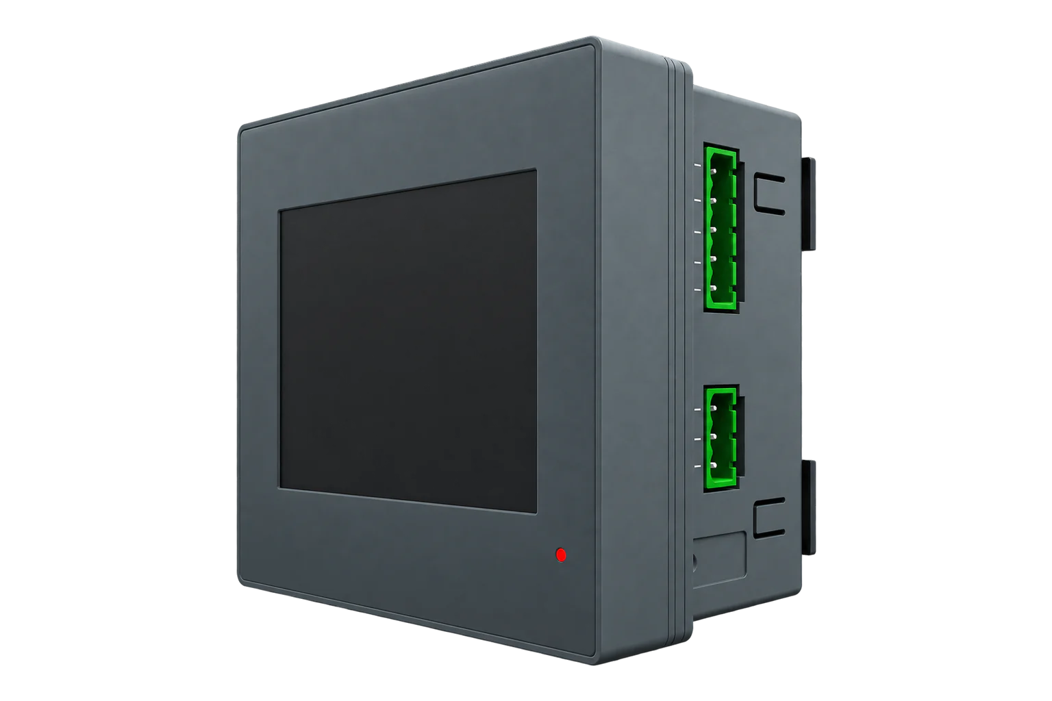
ABB's 96 × 96 mm panel network analysers for 1 A or 5 A current transformers, with Class 0.5S active energy, harmonics to the 40th and a colour display. The Modbus versions have an isolated RS-485 port; the Ethernet versions speak Modbus TCP.
Compatibility
Compatible with EpiSensor Edge over Modbus RTU and Modbus TCP.
Connect its RS-485 port to a Modbus Interface or to a serial interface on the Gateway, or use its Ethernet port for Modbus TCP. Edge polls it with its Modbus client.
Edge reads 32 values from it, listed under Interface.
Connect it with
-
Modbus Interface ZMB-3XFrom €399 ex VAT Configure Modbus Interface
-
Gateway ZGW-20From €899 ex VAT Configure Gateway
-
Evaluation Gateway on a Raspberry Pi Edge with one device licensedFree Set up Evaluation Gateway on a Raspberry Pi


Specifications
The M4M 20 and M4M 30 are ABB's panel-mounted network analysers for low-voltage switchboards. Both fit a 96 × 96 mm cutout, take a 48 to 240 V AC/DC auxiliary supply and measure up to 400 V phase to neutral and 690 V between phases directly. Current comes from x/1 A or x/5 A transformers, or from ABB's R4M Rogowski coils on the Rogowski versions. The M4M 20 has three current inputs and five buttons; the M4M 30 adds a fourth input for neutral and a touchscreen.12
- Power
- Mains. Auxiliary supply of 48 to 240 V AC or DC (±15 %), 50 or 60 Hz, 10 VA at most, protected by a T1 A fuse.1
- Active energy accuracy
- Class 0.5S (IEC 62053-22) with 5 A or 1 A CTs1
- Reactive energy accuracy
- Class 2S (IEC 62053-23)1
- Performance class
- IEC 61557-12 PMD/S/K70/0,5; voltage and current Class 0.21
- Voltage inputs
- 46 to 400 V AC L-N, 80 to 690 V AC L-L (+20 %), CAT III1
- Current inputs
- 3 on the M4M 20, 4 with neutral on the M4M 30; x/5 A or x/1 A, 50 mA to 6 A2
- Measurement
- True RMS to the 40th harmonic, 128 samples a cycle, refreshed every 25 cycles1
- Communication versions
- Modbus RTU, Modbus TCP, Profibus DP-V0 or BACnet/IP, each with Bluetooth Low Energy1
- Dimensions
- 96 × 96 × 77.5 mm, 57 mm deep inside the board1
- Protection
- IP54 front, IP20 terminals1
- Operating temperature
- -25 to 70 °C, up to 93 % RH non-condensing at 40 °C1
Where it is used
Incomers, feeders and motor control centres in low-voltage switchboards, on existing CTs or Rogowski coils.
Transformer and distribution board monitoringPower quality on circuits with drives, UPS systems and IT loads, with THD per phase.
Data centre power monitoring and PUE inputsBringing meters already on a Modbus RTU bus or the site network into a BMS or SCADA system through Edge.
Modbus meter integration for a BMS or SCADA system
Interface
This register map applies to the M4M 20 and M4M 30.
Communication settings
- Modbus RTU
- RS-485 with optical isolation, on the Modbus, I/O and Rogowski versions
- Connector
- 3-pole terminal: A, B and common
- Unit address
- 1 to 247
- Baud rate
- 9600, 19200, 38400, 57600 or 115200 bit/s
- Parity
- Even, odd or none
- Stop bits
- 1 or 2
- Modbus TCP
- RJ45 on the Ethernet versions, up to 3 clients
- TCP defaults
- DHCP off, 192.168.1.12, gateway 192.168.1.1, port 502
- Bluetooth
- Bluetooth Low Energy on every version, for set-up with ABB's apps
- Read with
- FC03 (holding registers)
- Word order
- High word first on each 32-bit value
- Addresses
- Zero-based PDU addresses, as sent on the bus
From M4M 20 network analyzer user manual (2CSG445032D0201)1 and M4M Modbus communication manual (2CSG445050D0201)3.
Register map
| Point | Address | Hex | Format | Scale | Unit |
|---|---|---|---|---|---|
| Voltage L1-N | 23298 | 0x5B02 |
UINT32 | ×0.1 | V |
| Voltage L2-N | 23300 | 0x5B04 |
UINT32 | ×0.1 | V |
| Voltage L3-N | 23302 | 0x5B06 |
UINT32 | ×0.1 | V |
| Voltage L1-L2 | 23304 | 0x5B08 |
UINT32 | ×0.1 | V |
| Voltage L3-L2 | 23306 | 0x5B0A |
UINT32 | ×0.1 | V |
| Voltage L1-L3 | 23308 | 0x5B0C |
UINT32 | ×0.1 | V |
| Current L1 | 23312 | 0x5B10 |
UINT32 | ×0.01 | A |
| Current L2 | 23314 | 0x5B12 |
UINT32 | ×0.01 | A |
| Current L3 | 23316 | 0x5B14 |
UINT32 | ×0.01 | A |
| Total Active Power | 23322 | 0x5B1A |
INT32 | ×0.01 | W |
| Active Power L1 | 23324 | 0x5B1C |
INT32 | ×0.01 | W |
| Active Power L2 | 23326 | 0x5B1E |
INT32 | ×0.01 | W |
| Active Power L3 | 23328 | 0x5B20 |
INT32 | ×0.01 | W |
| Total Reactive Power | 23330 | 0x5B22 |
INT32 | ×0.01 | var |
| Reactive Power L1 | 23332 | 0x5B24 |
INT32 | ×0.01 | var |
| Reactive Power L2 | 23334 | 0x5B26 |
INT32 | ×0.01 | var |
| Reactive Power L3 | 23336 | 0x5B28 |
INT32 | ×0.01 | var |
| Total Apparent Power | 23338 | 0x5B2A |
INT32 | ×0.01 | VA |
| Apparent Power L1 | 23340 | 0x5B2C |
INT32 | ×0.01 | VA |
| Apparent Power L2 | 23342 | 0x5B2E |
INT32 | ×0.01 | VA |
| Apparent Power L3 | 23344 | 0x5B30 |
INT32 | ×0.01 | VA |
| Frequency | 23346 | 0x5B32 |
UINT16 | ×0.01 | Hz |
| Total Power Factor | 23360 | 0x5B40 |
INT16 | ×0.001 | - |
| Power Factor L1 | 23361 | 0x5B41 |
INT16 | ×0.001 | - |
| Power Factor L2 | 23362 | 0x5B42 |
INT16 | ×0.001 | - |
| Power Factor L3 | 23363 | 0x5B43 |
INT16 | ×0.001 | - |
| Voltage THD L1 | 23808 | 0x5D00 |
UINT16 | ×0.1 | % |
| Voltage THD L2 | 23936 | 0x5D80 |
UINT16 | ×0.1 | % |
| Voltage THD L3 | 24064 | 0x5E00 |
UINT16 | ×0.1 | % |
| Current THD L1 | 24576 | 0x6000 |
UINT16 | ×0.1 | % |
| Current THD L2 | 24704 | 0x6080 |
UINT16 | ×0.1 | % |
| Current THD L3 | 24832 | 0x6100 |
UINT16 | ×0.1 | % |
ABB gives each value's first register in hexadecimal, exactly as it goes on the bus. The addresses on this page are the same numbers in decimal: Voltage L1-N at 0x5B02 is 23298.3
The meter reads any 1 to 125 registers between 0x1000 and 0x8EFF in one request. A value the connected model does not have reads as all ones if unsigned, or the highest positive number if signed.3
Energy totals are 64-bit unsigned counters in steps of 0.01 kWh, starting at 0x5000 for imported active energy. They are not in the Edge template, because Edge does not read 64-bit integers.4
Edge template
This JSON file supplies the register map. Applying it to an existing meter replaces its sensor list while retaining the site connection, unit ID and enable state.
| Model | Connection | Points | Version | Updated | Download |
|---|---|---|---|---|---|
| M4M 20 / M4M 30 | Modbus RTU over RS-485, Modbus TCP | 32 | 1.0.0 | Download |
Downloads need a signed-in account with Edge download access.
Use the template in Edge
- Import the JSON file
In Edge, open Settings, then Devices and Templates. Choose Import JSON and select the downloaded file. Confirm that the model and template name match your device.
- Load the map for your meter
For a new Modbus device, use Load Template before entering the manufacturer or model; it fills those fields and the register list. Set the name, site connection and unit ID, check the polling enable state, then test before saving. For an existing device, apply only to the matching model; this replaces its sensor list but retains its connection, unit ID and enable state.
- Test a reading
Use Test in the wizard and compare a known reading with the meter display. Check its unit, sign and scale, then confirm that timestamps keep advancing. These starter maps are read-only and leave exports off until you configure them.
Setup
-
Check the version
Only the Modbus, I/O and Rogowski versions have Modbus RTU on RS-485. Ethernet versions speak Modbus TCP; Profibus and BACnet versions do not speak Modbus.1
-
Commission the meter
On first power-up a wizard asks for language, password, date and time, network type, CT ratio and VT ratio. Set the CT ratio to your transformers before you read anything.2
-
Wire the bus
Connect A and B on the 3-pole terminal to a ZMB-31 or the Gateway's serial interface, with C to the common if you have one. Keep the bus under 700 m and stubs under 1 m, and terminate both ends with 120 Ω.3
-
Set address and speed
Under Communication > Modbus RTU, set an address from 1 to 247, the baud rate and the parity, then set Edge to match. On Ethernet versions, set the IP address or turn on DHCP under Communication > Modbus TCP/IP.1
-
Read one register
Import the template and read Voltage L1-N at 23298 (0x5B02) with function code 3. It is an unsigned 32-bit value in steps of 0.1 V, so 2301 means 230.1 V.4
-
Enable the map
Once voltage, current and total active power match the display, enable the rest of the map and watch several fresh readings before you add exports or alarms.
Common questions
- What are the M4M's RS-485 settings?
- Address 1 to 247; 9600, 19200, 38400, 57600 or 115200 bit/s; even, odd or no parity; 1 or 2 stop bits. Set them under Communication > Modbus RTU on the display.1
- Which function codes does the M4M support?
- Function code 3 to read holding registers, and 6 and 16 to write. After a write, read the value back: the meter does not report whether a write took effect, and silently ignores writes to settings the model does not have.3
- How are 32-bit values ordered?
- The most significant byte is in the high byte of the first register and the least significant byte in the low byte of the last. In Edge that is big-endian with no word or byte swap.3
Related devices


Sources
- M4M 20 network analyzer user manual (2CSG445032D0201) (opens in a new tab)
- M4M 30 and M4M 32 network analyzer user manual (2CSG445042D0201) (opens in a new tab)
- M4M Modbus communication manual (2CSG445050D0201) (opens in a new tab)
- M4M Modbus map, v1.3O (9AKK107492A7627) (opens in a new tab)
- ABB M4M 20 and M4M 30 register map (opens in a new tab)
Further reading
Product names and trademarks belong to their owners. Publication does not imply endorsement or a commercial relationship.