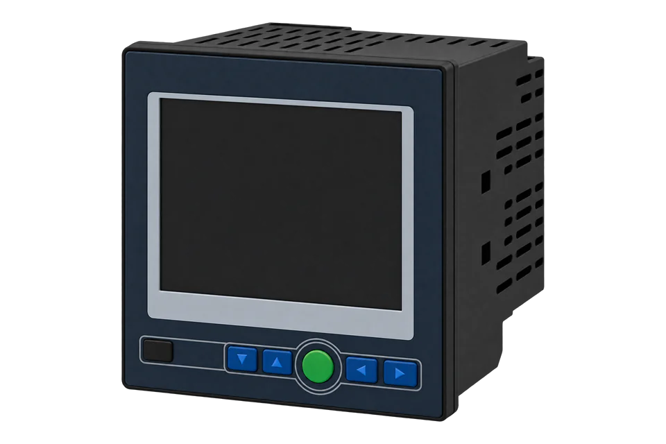
Accuenergy AcuDC 243
DC power and energy meter
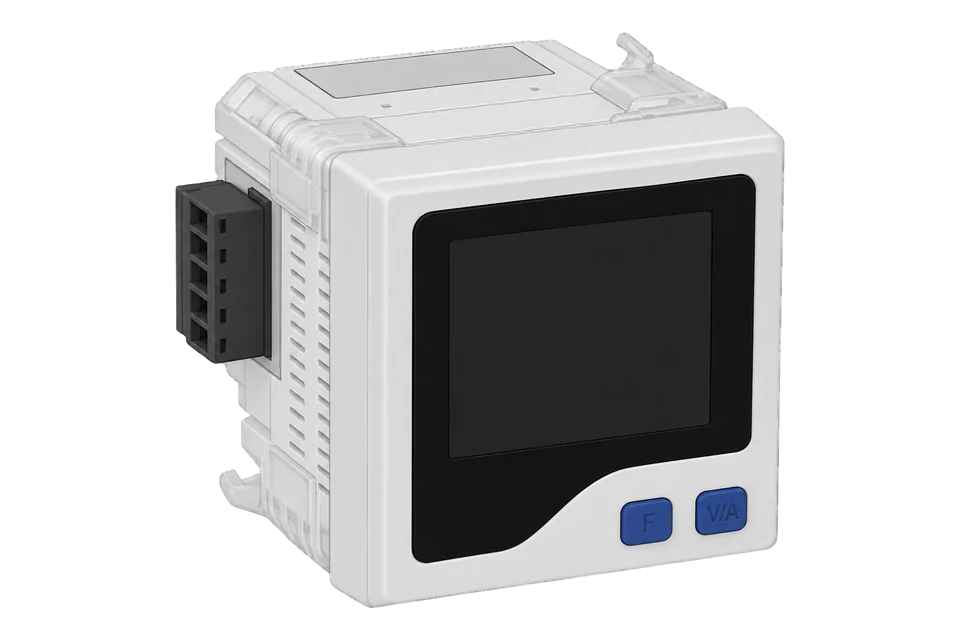
The AcuDC 240 series is Accuenergy's panel meter for DC systems such as battery and PV buses, EV chargers and telecom supplies, ordered as the AcuDC 243. It measures voltage up to 1000 V DC directly or 9999 V through a Hall effect sensor, and current in both directions directly up to ±10 A or up to ±50000 A through a 50 to 100 mV shunt or a Hall effect sensor. With the C communication option, an optically isolated RS-485 port on terminals 14, 15 and 16 runs Modbus RTU at 19200 bit/s, address 1, no parity by default. The manual's map gives voltage, current and power as 32-bit floats from 0x0200, high word first, and import, export, total and net energy and ampere-hours as 32-bit counters in hundredths from 0x0300.
Compatibility
Compatible with EpiSensor Edge over Modbus RTU (communication option C)
The AcuDC 243 with the C communication option is compatible with EpiSensor Edge over its RS-485 port running Modbus RTU, read through a ZMB-31 Modbus Interface or a Gateway serial port. Accuenergy's user manual prints the register map with hexadecimal and decimal addresses, data types and the scaling of every value, and works an FC03 voltage read.
AcuDC 243 meters ordered with the C (RS-485, Modbus RTU) option, any voltage, current, power supply and I/O option, using user manual V1.1.8 (December 2025) as a best-effort starting point. Site check: read voltage at 0x0200 and compare it with the display before adding points. Read-only monitoring: no writes to the settings, energy, Ah, counter or relay registers.
Connect it with


For a meter on a battery, PV or charger DC bus where a wireless link avoids running a data cable back to the Gateway
- Modbus
- Wireless
- Edge
- Platforms
When the Gateway sits near the meter, or several DC meters share one wired RS-485 bus
- Modbus
- Edge
- Platforms
Models
| Models | Interface | Route into Edge |
|---|---|---|
| AcuDC 243 - voltage - current - power supply - I/O - C - D, for example AcuDC 243-300V-A1-P1-X1-C-D | Voltage 1000V, 600V, 300V or 60V direct, or 5V through a voltage Hall effect sensor; current A0 (±10 A direct), A1 (50 to 100 mV shunt), A2 (4 to 20 mA or 12 mA ± 8 mA Hall sensor) or A3 (0 to ±5 V or ±4 V Hall sensor); P1 or P2 power supply; I/O X1 to X5; C: RS-485 with Modbus RTU; D: data logging | Read the floats from 0x0200 and the energy and Ah counters from 0x0300 with FC03 on the serial path. Set the full-range current and shunt values on the meter, not from Edge. |
| AcuDC 243-1000V-A1-P2-C-U, with 50 A to 1000 A shunts (0 to 75 mV) | The datasheet's EV charger version: 1000 V DC input, single-direction shunt options from 50 A to 1000 A and RS-485, shown with the P2 power supply | Same registers and serial path. Read import energy at 0x0300 for the energy delivered. |
| AcuDC 243 ordered without the C option | The manual says only meters with a communication option have address, baud rate and parity screens; without C there is no RS-485 port | No Modbus port: order the meter with C for an Edge connection. The analogue outputs of an X1 or X2 module can carry voltage, current or power as 4 to 20 mA or 0 to 5 V to a PLC or I/O module. |
Specifications
RS-485 with Modbus RTU is the C option. Plug-on I/O modules add two digital inputs with two analogue outputs, two relay outputs, two digital outputs or a ±15 V DC supply for Hall effect sensors, and the D option adds three data logs.12
- Order code
- AcuDC 243, then voltage (1000V, 600V, 300V or 60V direct; 5V through a Hall effect sensor), current (A0: 0 to ±10 A direct; A1: 50 to 100 mV shunt; A2: 4 to 20 mA or 12 mA ± 8 mA Hall sensor; A3: 0 to ±5 V or ±4 V Hall sensor), power supply (P1 or P2), I/O (X1 to X5), communication (C) and data logging (D). Examples: AcuDC 243-300V-A1-P1-X1-C-D, AcuDC 243-1000V-A1-P2-C-D.12
- Voltage input
- 0 to 1000 V DC direct, or 0 to 9999 V through a voltage Hall effect sensor. 2 MΩ input impedance, 10 V pickup.2
- Current input
- 0 to ±10 A direct (0.01 A pickup), or 0 to ±50000 A through a 50 to 100 mV shunt or a Hall effect sensor, with a programmable range.2
- Accuracy
- Voltage and current 0.2 %; power and energy 0.5 %, with 0.2 % on request. Drift below 100 ppm/°C.2
- Grounding
- With a current Hall effect input and direct voltage input, the AcuDC 243 supports only negative-grounded systems. Positive-grounded, ungrounded or centre-tap systems need an external voltage Hall effect sensor.2
- RS-485
- Half duplex, optically isolated (2500 V AC), on terminals 14 (A, +), 15 (B, -) and 16 (S, shield). Modbus RTU, address 1 to 247 (default 1), 1200 to 38400 bit/s (default 19200), no parity and one stop bit by default with even, odd or two stop bits selectable.12
- Control power
- P1: 100 to 240 V AC, 50/60 Hz, or 100 to 300 V DC. P2: 20 to 60 V DC. 3 W typical.2
- Housing
- 72 × 72 × 64.5 mm with a 68 × 68 mm panel cut-out; a DC-DIN adapter mounts it on a horizontal DIN rail.2
- Approvals
- Safety IEC 61010-1; EMC IEC 55011, IEC 61000-6-2, IEC 61000-3-2 and IEC 61000-3-3.2
- Environment
- Operating -25 to +70 °C, storage -40 to +85 °C, 5 to 95 % RH non-condensing.2
Interface
Documented measurements and integration boundaries for AcuDC 243.
- The manual prints each address in hexadecimal and decimal, and both are the same zero-based PDU address: 0200H is decimal 512 on the wire. A client that numbers holding registers from one shows it as register 513 (400513). Read measurements with FC03; relays use FC01 and FC05, digital inputs FC02 and settings FC16.
- Floats are IEEE 754 single precision in two registers, high word first: the manual's FC03 example returns 40 28 51 D8 for 2.63 V at 0200H. The manual notes that the high byte is followed by the low byte.
- Real-time floats: voltage 0x0200 (V), current 0x0202 (A, signed by direction), power 0x0204 (kW), analogue outputs AO1 and AO2 at 0x0206 and 0x0208 (V or mA). DI1 and DI2 pulse counts are UINT32 at 0x020A and 0x020C.
- Energy and charge, 32-bit long in two registers: import energy 0x0300, export energy 0x0302, total energy 0x0304 and net energy 0x0306 (signed), kWh = Rx / 100; import Ah 0x0308, export Ah 0x030A, total Ah 0x030C and net Ah 0x030E (signed), Ah = Rx / 100.
- Import energy is energy the load takes from the source and export is energy returned to it; total is their absolute sum and net their algebraic sum. With current in both directions, as on a battery bus, the import and export counters accumulate separately.
- The manual's Table B-17 scales energy as Rx / 100 kWh and its specification gives 0.01 kWh resolution; the September 2026 datasheet gives 0.0001 kWh. Compare one energy read with the display before setting the multiplier.
- Running time, long: meter running time 0x0280 and load running time 0x0282, hours = Rx / 100. On meters with the D data logging option the clock is at 0x0284 to 0x0289, maximum values with timestamps from 0x0400 and minimum values from 0x0460.
- Settings read with FC03: password 0x0100, device address 0x0101, baud rate 0x0102, parity 0x0103 (3 = no parity, 1 stop bit), full-range current 0x0104 (A), full-range shunt 0x0105 (mV) and full-range voltage 0x0107.
- Settings accept FC16, the energy and Ah counters are R/W, 0x0122, 0x0127 and 0x0126 clear energy, Ah and DI counts, and relays accept FC05. Keep all of them out of a monitoring poll.
Assessment
AcuDC 243 meters with the C (RS-485, Modbus RTU) option, using user manual V1.1.8 as a best-effort starting point. Read-only monitoring.
- InteroperabilityWell supported
- Accuenergy documents Modbus RTU on the RS-485 option and prints the register map in the manual with hexadecimal and decimal addresses, data types, scaling and a worked FC03 frame that fixes the high-word-first float order.1
- AccuracySupported with conditions
- 0.2 % voltage and current and 0.5 % power and energy, with bidirectional current, separate import and export energy and Ah, and inputs for shunts and Hall effect sensors. Accuracy depends on the shunt or sensor, the full-range settings and the grounding scheme, and the energy resolution differs between the manual and the datasheet.12
- SecurityNot yet assessed
- A password (0 to 9999, register 0x0100) protects the settings screens. Settings and the energy counters are writable over Modbus.1
- ReliabilitySupported with conditions
- The datasheet lists EMC to IEC 61000-6-2, IEC 61000-3-2 and IEC 61000-3-3, the RS-485 port is isolated to 2500 V AC and settings are kept in non-volatile EEPROM through a power loss. The manual lists no Modbus exception codes or response time, so treat failed reads as missing data.12
- RuggednessSupported with conditions
- Rated -25 to +70 °C operating and 5 to 95 % RH non-condensing in a 72 × 72 mm panel housing. Install inside a suitable panel or enclosure.2
- ScalabilitySupported with conditions
- Addresses 1 to 247 on a daisy-chained RS-485 bus of up to 1200 m. Each meter covers one DC circuit, so a site with many strings or batteries needs one meter per circuit.1
Setup
Read voltage from address 0x0200
AcuDC 240 user manual V1.1.8, Appendix B.3, lists voltage at 0200H to 0201H (decimal 512 to 513) as a float read with function code 03, real value = Rx in volts. Tables B-8 and B-9 work this read for a meter at address 1. Use it as the starting point and compare the result with the display.
- Request
- 01 03 02 00 00 02 C5 B3: Modbus address 1, FC03, address 0x0200, two registers, RTU CRC C5 B3.
- Address convention
- Send 0x0200 as printed: it is the zero-based PDU address 512, and the manual's decimal column gives the same number. A client that numbers holding registers from one shows it as register 513 (400513). Do not send decimal 200.
- Documented response
- 01 03 04 40 28 51 D8 52 31: four data bytes, high word 40 28 first, then low word 51 D8, RTU CRC 52 31.
- Decode
- IEEE 754 float, high word first: 0x402851D8 = 2.63 V (the manual prints 2.6299953 V). A client that swaps the words reads 0x51D84028, about 1.2 × 10¹¹, so a voltage of that size means the word order is wrong.
- Acceptance
- Keep the point when the voltage agrees with the display at the same time. If it does not, check the address, word order and voltage range option before adding current, power and energy.
Acceptance: The bytes are the manual's own example, with CRCs that check, not a captured reply from a site meter. A real reply must agree with the display before current, power and energy points are enabled.
-
Check the order code
Confirm the label includes C, the RS-485 option. Note the voltage and current options and, for a shunt meter, the full-range current and shunt voltage set on the meter.
-
Read the communication settings
Press F and V/A together for the parameter setting mode and step through the address, bPS (baud rate) and CHEC (parity) screens: address 1, 19200 bit/s and no parity by default. Enter the same values in Edge or the ZMB-31 and leave the meter's settings as they are.
-
Wire the RS-485 pair
Connect A (+) to terminal 14, B (-) to 15 and the shield to S on 16, A to A and B to B along the bus. Give each meter its own address.
-
Make a voltage read
Read two registers at 0x0200 with FC03 and decode a float, high word first, as in the worked read below. Compare the result with the voltage on the display.
-
Add current, power and energy
Add current at 0x0202 and power at 0x0204, then import and export energy at 0x0300 and 0x0302 with the Rx / 100 scale, checking one counter against the display. Keep FC05 and FC16 writes out of the polling configuration.
Common questions
- Should energy be divided by 100?
- The manual's Table B-17 says energy is Rx / 100 in kWh and Ah is Rx / 100. The datasheet quotes a finer 0.0001 kWh resolution, so compare one counter with the display before setting the multiplier.12
- Does every AcuDC 243 have Modbus?
- No. RS-485 with Modbus RTU is the C option in the order code, and the manual says only meters with a communication option show address, baud rate and parity screens.12
- Why does voltage read as a huge number?
- The client is taking the low word first. The AcuDC sends floats high word first, as in the manual's example where 40 28 51 D8 is 2.63 V. Set the point to big-endian word order.1
Related devices



Sources
- AcuDC 240 Series Power and Energy Meter user's manual, V1.1.8, revised December 2025 (document 5060E2101) (opens in a new tab) (PDF)
- AcuDC 240 DC Power & Energy Meter datasheet, version 1.0.14, revised September 2026 (opens in a new tab) (PDF)
Further reading
- ApplicationBattery storage performance monitoring
- ApplicationSolar PV monitoring
- ToolModbus register address translator
- ToolModbus data decoder
- ToolBattery autonomy calculator
- GuideModbus commissioning over RS-485
- ToolRS-485 termination and bias
- ManufacturerAccuenergy devices
- ProtocolModbus devices and register maps
- CategoryEnergy meters
Product names and trademarks belong to their owners. Publication does not imply endorsement or a commercial relationship.