Accuenergy Acuvim CL and EL
Three-phase power meter
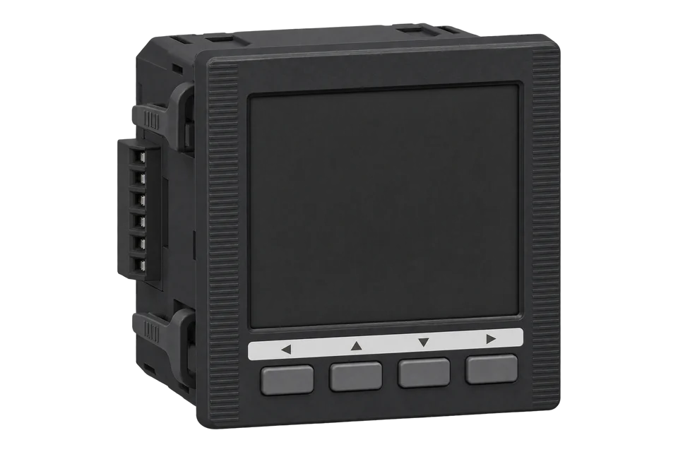
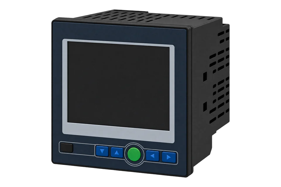
The Acuvim L series is Accuenergy's three-phase multifunction meter for panels and switchboards, sold today as the Acuvim CL (active energy class 0.5S, harmonics to the 31st) and the Acuvim EL (class 0.2S, harmonics to the 63rd and power quality event logging). Both come as a 96 × 96 mm panel meter with an LCD (D) or as a DIN-rail transducer without a display (M), for 5 A/1 A CTs or 333 mV and Rogowski coil sensors. The built-in, optically isolated RS-485 port on terminals 14, 15 and 16 runs Modbus RTU at 19200 bit/s, address 1, no parity, by default. Accuenergy's CL and EL map gives voltage, current, power and power factor as IEEE 754 floats from 0x4000, high word first, and energy as 32-bit counters from 0x4048. The meter ships in Secondary reading mode, so Modbus voltage and current arrive before the PT and CT ratios unless the installer has switched it to Primary mode.
Compatibility
Compatible with EpiSensor Edge over Modbus RTU, or Modbus TCP through an AXM Ethernet module
The Acuvim CL and EL are compatible with EpiSensor Edge over the built-in RS-485 port running Modbus RTU, read through a ZMB-31 Modbus Interface or a Gateway serial port. Accuenergy publishes the CL and EL Modbus map with hexadecimal and decimal addresses, data types, the Primary and Secondary scaling formulas, and a manual whose FC03 example decodes floats high word first. An optional AXM-WEB2 or AXM-NET2 module adds Modbus TCP.
Acuvim CL and EL meters with V4 power supply codes (P1V4 or P2V4), panel (D) or DIN-rail (M), on the built-in RS-485 port with channel 1 set to Modbus, using the CL and EL Modbus map version 1.02 and user manual V 4.1.12 as a best-effort starting point. Site check: read frequency at 0x4000 and compare the first voltage read with the display before adding points. Read-only monitoring: no writes to the settings, clock, energy, reset or relay registers.
Connect it with


For a meter in a switchboard or distribution board where a wireless link avoids running a data cable back to the Gateway
- Modbus
- Wireless
- Edge
- Platforms
When the Gateway sits near the meter, or several meters share one wired RS-485 bus
- Modbus
- Edge
- Platforms
When the meter already carries an AXM Ethernet module, or the site network is closer than a serial run
- Modbus
- Edge
- Platforms
Models
| Models | Interface | Route into Edge |
|---|---|---|
| Acuvim-CL-D-5A-P1V4 | Acuvim-CL: active energy class 0.5S (IEC 62053-22) and class 0.5 (ANSI C12.20), harmonics to the 31st. D: panel-mount meter with LCD display. 5A: 5 A or 1 A CT secondaries, selectable in the field. P1V4: control power 100 to 415 V AC, 50/60 Hz, or 100 to 300 V DC. No -S suffix, so no anti-tampering seal. Built-in RS-485 with Modbus RTU or BACnet MS/TP; no module is part of this code. | Read the float block from 0x4000 and the energy counters from 0x4048 with FC03 over the built-in RS-485 port. Set the CT ratio on the meter (CT1 primary, CT2 = 5 or 1) and check the reading mode before scaling. |
| Acuvim-CL-D or -M, 5A or mV, P1V4 or P2V4 | D (LCD panel meter) or M (DIN-rail transducer without display, with an optional remote display); 5A (5 A/1 A) or mV (333 mV and Rogowski coil); P1V4 (100 to 415 V AC, 100 to 300 V DC) or P2V4 (20 to 60 V DC); 8 MB data logging | Same registers and serial path. On an mV meter CT2 is 333 or 100, but the map's ratio formulas use CT2 = 1 for those sensors. |
| Acuvim-EL-D or -M, 5A or mV, P1V4 or P2V4 | The same housings, inputs and RS-485 port as the CL, with active energy class 0.2S and 0.2, harmonics to the 63rd, voltage sag and swell event logging and 16 MB of memory | Same read path and addresses. Power quality event records are not needed for energy monitoring; keep them out of the poll. |
| Acuvim-BL and Acuvim L meters ordered without a V4 power supply code | The V3.06 manual describes the Acuvim-BL as the basic model with a digital output terminal strip and no communication terminal strip; earlier CL and EL meters are described by that manual | Read an earlier CL or EL from the V3.06 manual's own tables and compare the first read with the display. An Acuvim-BL has no Modbus port: meter the same circuit with an EpiSensor meter instead. |
Specifications
The built-in RS-485 port carries Modbus RTU or BACnet MS/TP. Up to three plug-in AXM modules add a second RS-485 port, Ethernet with Modbus TCP and BACnet/IP, or digital and analogue I/O.13
- Order code
- Model (Acuvim-CL or Acuvim-EL), mounting (D: LCD panel meter; M: DIN-rail transducer without display), current input (5A: 5 A/1 A; mV: 333 mV and Rogowski coil) and power supply (P1V4: 100 to 415 V AC, 50/60 Hz, 100 to 300 V DC; P2V4: 20 to 60 V DC). Add -S for the anti-tampering seal. Examples: Acuvim-CL-D-5A-P1V4, Acuvim-CL-M-mV-P2V4, Acuvim-EL-D-5A-P1V4.13
- Voltage inputs
- The June 2026 datasheet gives 480 V AC L-N and 828 V AC L-L nominal full scale; the March 2026 manual appendix gives 400 V AC L-N and 690 V AC L-L (+20 %). 45 to 65 Hz, 2 MΩ per phase. Higher voltages need PTs.13
- Current inputs
- Four channels: 5 A or 1 A CT secondaries (0 to 10 A and 0 to 2 A metering range), 333 mV or Rogowski coil (0 to 400 mV). Withstand 20 A RMS continuous. Every model needs external CTs or sensors.3
- Accuracy
- Acuvim CL: active energy class 0.5S to IEC 62053-22 and class 0.5 to ANSI C12.20. Acuvim EL: class 0.2S and class 0.2. Both: reactive energy class 2 to IEC 62053-23, voltage and current 0.1 %.13
- RS-485
- Half duplex, optically isolated, on terminals 14 (A, +), 15 (B, -) and 16 (S, shield). Modbus RTU by default or BACnet MS/TP. Address 1 to 247 (default 1), 2400 to 115200 bit/s (default 19200), parity None1 by default with even, odd or None2 selectable.12
- Bus
- Up to 32 devices on one RS-485 bus and 1200 m of shielded twisted pair, AWG22 (0.32 mm²) or heavier. Avoid T branches and earth the shield at one end only.1
- Optional modules
- AXM-RS485 (second Modbus RTU port), AXM-WEB2, AXM-WEB2-D and AXM-WEB2-FOLC (Modbus TCP, BACnet/IP, web server and data post), AXM-NET2 (Modbus TCP), AXM-IO1 to AXM-IO3 (digital, relay and analogue I/O). At most three modules per meter, the communication module first.3
- Memory
- Acuvim CL: 8 MB for data logging. Acuvim EL: 16 MB (8 MB data logging and 8 MB power quality), with up to 50,000 sag and swell events.13
- Approvals
- Measurement IEC 62053-22, ANSI C12.20 and IEC 61557-12; safety IEC 61010-1 and UL 61010-1; CE and RoHS; BTL listed (B-SA) for the Acuvim CL and EL. No MID approval is listed.3
- Housing
- 96 × 96 × 64.3 mm with a 92 × 92 mm panel cut-out, or an ANSI C39.1 4 inch round cut-out; 51 mm deep behind the panel. An optional cover raises the display to IP66 or NEMA 4X.13
- Environment
- Operating -25 to +70 °C, storage -40 to +85 °C, 5 to 95 % RH non-condensing. Control power installation category III, burden 5 W.3
Interface
Documented measurements and integration boundaries for Acuvim CL and EL.
- The map prints each address in hexadecimal and decimal, and both are the same zero-based PDU address: 4002H is decimal 16386 on the wire. A client that numbers holding registers from one shows it as register 16387 (416387). Read measurements with FC03; the manual lists function codes 01, 02, 03, 05 and 16, not 04.
- Float values are IEEE 754 single precision in two registers, high word first: the manual's FC03 example returns 42 48 00 00 for 50.00 Hz at 4000H. dword values are high word first as well (high word × 65536 + low word).
- Frequency at 0x4000; phase voltages Ua, Ub and Uc at 0x4002, 0x4004 and 0x4006 with their average at 0x4008; line voltages Uab, Ubc and Uca at 0x400A, 0x400C and 0x400E with their average at 0x4010: float, hertz and volts.
- Phase currents Ia, Ib and Ic at 0x4012, 0x4014 and 0x4016, average current at 0x4018 and neutral current at 0x401A: float, amperes.
- Active power per phase at 0x401C, 0x401E and 0x4020 with the total at 0x4022; reactive power at 0x4024 to 0x402A; apparent power at 0x402C to 0x4032: float. The map's relationship is P = Rx / 1000 in kW, so the register holds watts, var or VA.
- Power factor per phase and total at 0x4034, 0x4036, 0x4038 and 0x403A; voltage and current unbalance at 0x403C and 0x403E (Rx × 100 %); active, reactive and apparent power demand at 0x4042, 0x4044 and 0x4046: float.
- In Secondary mode (the default, 0 at 0x101D) multiply voltages by PT1/PT2, currents by CT1/CT2 and powers by both. In Primary mode (1 at 0x101D) the floats are already primary values. With 333 mV or Rogowski sensors, use CT2 = 1 in these formulas, as the manual instructs.
- Import and export active energy at 0x4048 and 0x404A, import and export reactive energy at 0x404C and 0x404E, total active energy at 0x4050, net active energy at 0x4052 (INT32) and apparent energy at 0x4058: 32-bit, high word first. Per-phase active energy runs from 0x4620 (phase A import) to 0x462B (phase C export).
- Energy scaling follows the Energy Display Mode at 0x1019: in Primary mode (0, the default) kWh = Rx / 10; in Secondary mode (1) or Primary 0.001 kWh mode (2) kWh = Rx / 1000.
- The map also gives a one-register Int16 copy of the basic measurements from 0x3200 (frequency Rx / 100 Hz, voltage Rx × (PT1/PT2) / 10 V, current Rx × (CT1/CT2) / 1000 A, power Rx × (PT1/PT2) × (CT1/CT2) W).
- The V 4.1.12 manual's Tables 6-19 and 6-20 print a second float block from 0x2180 (frequency 0x2180, phase 1 voltage 0x2182) and energy counters from 0x2080 (import 0x2080, export 0x2082). Its own FC03 example reads 0x4000, the block the November 2026 map gives, so start there.
- Identity: the SunSpec common block starts at 0xC350 with the ID 0x53756E53 (SunS), the manufacturer string at 0xC354 (16 registers), the model at 0xC364 (Acuvim-L in the manual) and the options string at 0xC374 (Acuvim-CL/EL).
- Settings from 0x0FFD read with FC03: protocol at 0x0FFE (0 Modbus), parity at 0x0FFF (3 None1), address at 0x1001, baud rate at 0x1002, PT1 at 0x1005 and 0x1006, PT2 at 0x1007, CT1 at 0x1008 and CT2 at 0x1009. Settings, the clock at 0x103F to 0x1045 and the energy counters accept FC16 writes, and relays accept FC05: keep them out of a monitoring poll.
Assessment
Acuvim CL and EL meters with V4 power supply codes, panel (D) or DIN-rail (M), on the built-in RS-485 port with channel 1 set to Modbus, using the CL and EL Modbus map version 1.02 and user manual V 4.1.12 as a best-effort starting point. Read-only monitoring.
- InteroperabilityWell supported
- Accuenergy documents Modbus RTU on the built-in RS-485 port and publishes a downloadable CL and EL map with hexadecimal and decimal addresses, FC03, data types and the Primary and Secondary scaling for every measurement. The manual's worked FC03 example fixes the high-word-first float order. Its register tables also print a second block from 0x2180, so confirm the block on the first read.12
- AccuracySupported with conditions
- Class 0.5S (CL) or 0.2S (EL) active energy with per-phase voltage, current, power, power factor and a fourth current input. Readings depend on correctly set CT and PT ratios and on scaling that matches the meter's reading mode and energy mode.13
- SecurityNot yet assessed
- A four-digit password protects settings on the display, an anti-tampering seal is an ordering option and the seal state is readable at 0x101F, but settings, the clock and the energy counters are writable over Modbus.12
- ReliabilitySupported with conditions
- The datasheet lists EMC immunity to IEC 61000-4-2, -3, -4, -5, -6, -8 and -11 and IEC 61000-6-2, and environmental testing to IEC 60068-2. Settings are stored in EEPROM and kept through a power loss. The RS-485 port is optically isolated and every frame carries a CRC. The manual lists no exception codes or response time, so treat failed reads as missing data.13
- RuggednessSupported with conditions
- Rated -25 to +70 °C operating and 5 to 95 % RH non-condensing, with installation category III control power and an optional IP66 or NEMA 4X display cover. Install inside a suitable panel.13
Setup
Read frequency, V1 and V2 from address 0x4000
The Acuvim CL and EL Modbus map version 1.02 lists frequency at 4000H to 4001H (decimal 16384 to 16385), phase A voltage at 4002H to 4003H and phase B voltage at 4004H to 4005H, all FC03 floats. Manual V 4.1.12, Tables 6-8 and 6-9, works the same read for a meter at address 17. Use it as the starting point and compare the result with the display.
- Request
- 11 03 40 00 00 06 D2 98: Modbus address 17, FC03, address 0x4000, six registers, RTU CRC D2 98.
- Address convention
- Send 0x4000 as printed: it is the zero-based PDU address 16384, and the map's decimal column gives the same number. A client that numbers holding registers from one shows it as register 16385 (416385). Do not send decimal 4000.
- Documented response
- 11 03 0C 42 48 00 00 42 C7 CC CD 42 C8 33 33 CA 7F: twelve data bytes, three floats, each high word first, RTU CRC CA 7F.
- Decode
- 0x42480000 = 50.00 Hz, 0x42C7CCCD = 99.9 V and 0x42C83333 = 100.1 V, IEEE 754 single precision, high word first. In Secondary mode multiply the voltages by PT1/PT2; with no PTs the ratio is 1. A client that swaps the words reads 0x00004248, about 2.4 × 10⁻⁴¹, for the frequency.
- Acceptance
- Keep the points when frequency and both voltages agree with the meter display at the same time. If they do not, check the address, word order, reading mode and ratios before adding current, power and energy.
Acceptance: The bytes are the manual's own example, with CRCs that check, not a captured reply from a site meter. A real reply must agree with the display before current, power and energy points are enabled.
-
Decode the order code
Read the label: CL or EL, D or M, 5A or mV, and P1V4 or P2V4. A code ending in V4 matches the V 4.1.12 manual. Note the CT and PT ratios on the settings pages; the settings password is 0000 unless the installer changed it.
-
Read the serial and reading-mode settings
Page S01 shows the Modbus address and S02 the baud rate; the parity and the channel 1 protocol (Modbus or BACnet) follow in the same SYS list. Check the Modbus reading mode (S31 PARA MODE, register 0x101D) and the energy mode (S27, register 0x1019). Enter the same serial values in Edge or the ZMB-31 and leave the meter's settings as they are.
-
Wire the RS-485 pair
Connect A (+) to terminal 14, B (-) to 15 and the shield to S on 16, A to A and B to B along the bus. Give each meter its own address and add a terminating resistor beside the last meter only if the signal is distorted.
-
Make two reads
Read frequency and two phase voltages from 0x4000 for six registers and decode the floats high word first, as in the worked read below. Compare the voltages with V1 and V2 on the display.
-
Add the points you need
Add current, power and energy from the same map, applying the CT and PT ratios if the meter is in Secondary mode and the divisor that matches the energy mode. Keep FC05 and FC16 writes out of the polling configuration.
Common questions
- What does Acuvim-CL-D-5A-P1V4 mean?
- Acuvim-CL is the class 0.5S model with harmonics to the 31st. D is the panel-mount meter with an LCD display. 5A means 5 A or 1 A CT secondaries, selectable in the field. P1V4 is the 100 to 415 V AC, 50/60 Hz or 100 to 300 V DC power supply of the V4 hardware. Without a -S suffix there is no anti-tampering seal, and modules are ordered separately.13
- Is the Acuvim CL part of the Acuvim L series?
- Yes. The manual names two standard Acuvim-L models, the Acuvim-CL and the Acuvim-EL. They share the housing, inputs, RS-485 port and the CL and EL Modbus map; the EL adds class 0.2S accuracy, harmonics to the 63rd and power quality event logging.12
- Why is current far lower than the display shows?
- The meter is in Secondary mode, its default, so Modbus floats arrive before the CT and PT ratios. Multiply current by CT1/CT2, voltage by PT1/PT2 and power by both, or have the installer set Basic Parameter Mode (S31 PARA MODE, register 0x101D) to Primary on the meter. The display is not affected by this setting.12
- Should energy be divided by 10 or by 1000?
- It depends on the Energy Display Mode at 0x1019 (page S27). In Primary mode, the default, kWh is the register value divided by 10. In Secondary mode or Primary 0.001 kWh mode, divide by 1000. Read 0x1019 once during commissioning and set the scale to match.12
- The manual shows voltage at 0x2182 but the map shows 0x4002. Which is right?
- Start with 0x4002. The November 2026 map gives the float block from 0x4000 and the manual's own FC03 example reads 4000H. The manual's register tables also print a block from 0x2180 and energy from 0x2080. If 0x4000 does not answer or does not match the display, read 0x2180 and compare that instead.12
Related devices



Sources
- Acuvim-L Multifunction Power and Energy Meter user manual, V 4.1.12, revised March 2026 (opens in a new tab) (PDF)
- Acuvim CL and EL Modbus map, version 1.02, 4 November 2026 (spreadsheet) (opens in a new tab)
- Acuvim L Multifunction Power & Energy Meter datasheet, version 2.0.18, revised June 2026 (opens in a new tab) (PDF)
- Acuvim-L Multifunction Power and Energy Meter user's manual, V3.06, revised December 2025 (opens in a new tab) (PDF)
Further reading
- ApplicationTransformer and distribution-board monitoring
- ToolModbus register address translator
- ToolModbus data decoder
- ToolCT ratio and burden calculator
- GuideModbus commissioning over RS-485
- ToolRS-485 termination and bias
- ManufacturerAccuenergy devices
- ProtocolModbus devices and register maps
- CategoryEnergy meters
Product names and trademarks belong to their owners. Publication does not imply endorsement or a commercial relationship.