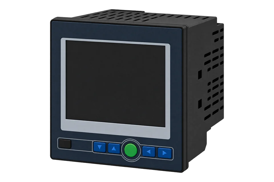
Accuenergy AcuRev 2000
Multichannel energy meter
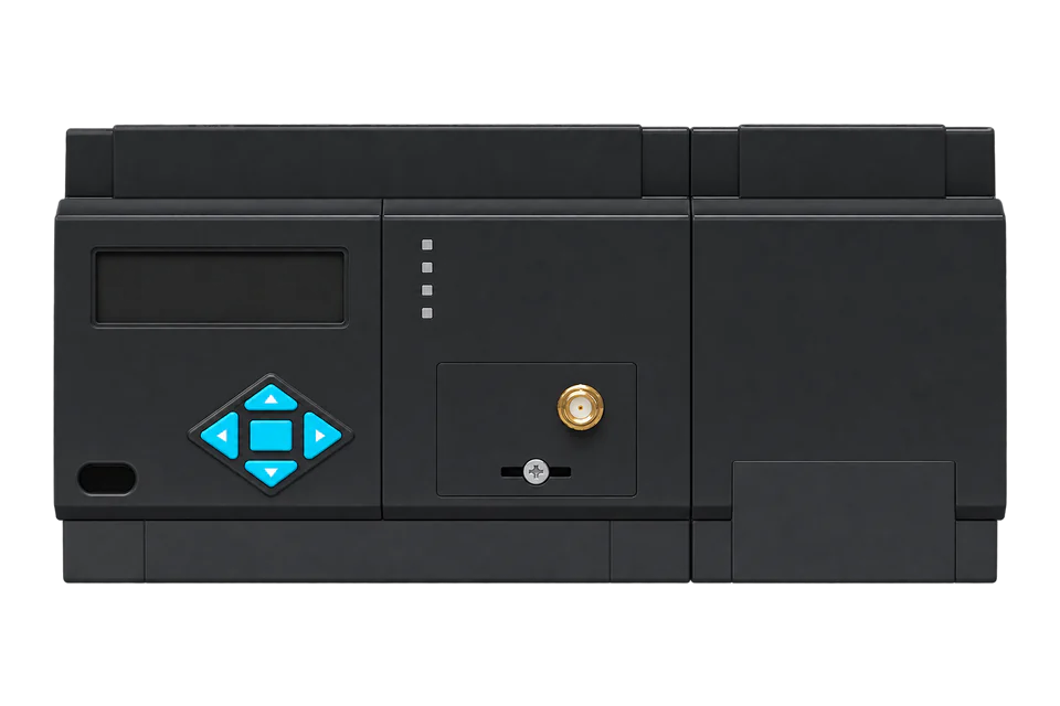
The AcuRev 2000 series is Accuenergy's multi-circuit submeter: one DIN-rail meter base measures the incoming supply (the inline circuit) and up to 18 single-phase or 6 three-phase tenant circuits through one or two EM current modules. Accuenergy sells it today as the AcuRev 2020, with 9 or 18 channels for 333 mV or Rogowski coil sensors, RS-485 only (Mod) or Ethernet, Wi-Fi and RS-485 (WEB), and a built-in or remote display. The RS-485 port on terminals 1, 2 and 3 runs Modbus RTU at 9600 bit/s, address 1, no parity by default. The manual's map gives inline voltage, current and power as 32-bit floats from 0x2000, each channel's current, power and power factor in a 12-register block from 0x2100, and energy as 32-bit counters in 0.1 kWh from 0x2500.
Compatibility
Compatible with EpiSensor Edge over Modbus RTU, or Modbus TCP on the WEB option
The AcuRev 2000 series is compatible with EpiSensor Edge over its RS-485 port running Modbus RTU, read through a ZMB-31 Modbus Interface or a Gateway serial port, and over Modbus TCP on meters with the Ethernet (WEB) option. Accuenergy's user manual prints the full register map with hexadecimal addresses, data types, word order and the energy scale, and works an FC03 energy read.
AcuRev 2020 meters (and the AcuRev 2010 described in the same manual, for power and energy) with 9 or 18 channels, on the RS-485 port or the Ethernet module, using user manual V2.12 (December 2025) as a best-effort starting point. Site check: read inline energy at 0x2500 and compare it with the display before adding channels. Read-only monitoring: no writes to the settings, clock, energy, reset or relay registers.
Connect it with


For a meter in a tenant distribution board where a wireless link avoids running a data cable back to the Gateway
- Modbus
- Wireless
- Edge
- Platforms
When the Gateway sits near the meter, or several meters share one wired RS-485 bus
- Modbus
- Edge
- Platforms
For an AcuRev 2020 ordered with the WEB communication option (Ethernet, Wi-Fi and RS-485)
- Modbus
- Edge
- Platforms
Models
| Models | Interface | Route into Edge |
|---|---|---|
| AcuRev 2020-1EM and 2020-2EM, Mod or WEB, D or E | 1EM: 9 circuits and 2EM: 18 circuits on external 333 mV CTs. Mod: RS-485 only; WEB: Ethernet, Wi-Fi and RS-485. D: built-in display; E: external remote display. Example: 2020-2EM-WEB-D. | Read the inline block from 0x2000, each channel's block from 0x2100 and energy from 0x2500 with FC03 over RS-485, or over Modbus TCP on a WEB meter. |
| AcuRev 2020-1EM-RCT and 2020-2EM-RCT | 9 or 18 circuits on flexible Rogowski coils. The brochure notes that THD and individual harmonics are not available with the RCT input. | Same registers and paths; leave the harmonic registers out of the poll. |
| AcuRev 2010, and meter bases with DM direct-connection modules | The manual describes the AcuRev 2010 as the basic measurement model, with power-related measurements only, and DM modules for direct connection at 20 (80) A per tenant | Read power and energy from the same addresses; power quality registers apply to the AcuRev 2020 only. |
Specifications
RS-485 with Modbus RTU is built in. The WEB option adds Ethernet and Wi-Fi with Modbus TCP, BACnet/IP, an HTTPS web server and data post. The meter also has an infrared port on the display for meter reading, eight digital inputs for water and gas pulse counting and two pulse outputs.12
- Order code
- Model (2020), current input (1EM: 9 circuits on 333 mV CTs; 2EM: 18 circuits on 333 mV CTs; 1EM-RCT and 2EM-RCT: 9 or 18 circuits on Rogowski coils), communication (Mod: RS-485 only; WEB: Ethernet, Wi-Fi and RS-485) and display (D: built-in; E: external remote). Example: 2020-2EM-WEB-D.2
- Voltage inputs
- 400 V AC L-N and 690 V AC L-L, CAT III, 45 to 65 Hz, 2 MΩ per phase. Fuse the voltage inputs at 1 A.1
- Current inputs
- EM modules for external CTs (333 mV split-core CTs or Rogowski coils on current models; the manual also lists 20 A to 1000 A solid-core CTs) or DM modules for direct connection at 20 (80) A per tenant.12
- Accuracy
- The August 2023 brochure gives active energy class 0.5S to IEC 62053-22 and class 0.5 to ANSI C12.20, with voltage, current and power at 0.5 %. The December 2025 manual appendix gives 1 % for real energy and power and lists IEC 62053-21 as the measurement standard.12
- RS-485
- Terminals 1 (A, +), 2 (B, -) and 3 (S, shield). Modbus RTU, address 1 to 247 (default 1), 1200 to 38400 bit/s (default 9600), no parity and one stop bit by default with even, odd or two stop bits selectable. Up to 1200 m of shielded twisted pair, AWG22 (0.32 mm²).1
- Ethernet (WEB option)
- 10/100 Mbit/s RJ45. Modbus TCP server on port 502 by default (user range 2000 to 5999), device address the same as the meter; HTTP on port 80, SMTP, SNMP and SNTP.1
- I/O
- Eight dry-contact digital inputs (pulse counting or status), two kWh pulse outputs, a second pulse and a demand period output.12
- Control power
- 100 to 415 V AC, 50/60 Hz, or 100 to 300 V DC, on terminals L, N and G. Fuse at 1 A, 250 V AC, time delay.1
Interface
Documented measurements and integration boundaries for AcuRev 2000.
- The manual prints addresses in hexadecimal and sends them as printed: its FC03 example reads 2500H by sending 25 00. A client that numbers holding registers from one shows 0x2500 (decimal 9472) as register 9473 (409473). Read measurements with FC03; the manual lists function codes 01, 02, 03, 05 and 16.
- Floats are 32-bit single precision in two registers and dwords are 32-bit unsigned in two registers, high bytes followed by low bytes in both cases: Rx = high word × 65536 + low word. Voltage, current, frequency and power factor floats equal the real value.
- Inline (incoming supply) floats: frequency 0x2000; phase voltages U1, U2 and U3 at 0x2002, 0x2004 and 0x2006 with their average at 0x2008; line voltages U12, U23 and U31 at 0x200A, 0x200C and 0x200E with their average at 0x2010; phase currents at 0x2012, 0x2014 and 0x2016 with their average at 0x2018.
- Inline system active, reactive and apparent power at 0x201A, 0x201C and 0x201E and system power factor at 0x2020; per-phase active power at 0x2024, 0x2026 and 0x2028, reactive at 0x202A to 0x202E, apparent at 0x2030 to 0x2034 and power factor at 0x2036 to 0x203A.
- Single-phase channels 1 to 18: each has six floats in a 12-register block starting at 0x2100 + 12 × (n - 1): current at +0, active power at +2, reactive power at +4, apparent power at +6, power factor at +8 and load nature at +10. Channel 1 power is 0x2102, channel 2 power 0x210E and channel 3 power 0x211A, the addresses the manual's logging example uses.
- Three-phase users 1 to 6 (channels grouped by the wiring setting at 0x888): total active power, reactive power, apparent power, power factor and load nature in a 10-register block starting at 0x21D8 + 10 × (k - 1).
- The manual gives no unit for the real-time power floats; it lists demand in kW and the display shows power in kW. Compare one channel's power with the display before scaling.
- Active energy, dword, kWh = Rx / 10: inline phases A, B and C at 0x2500, 0x2502 and 0x2504 and the inline system total at 0x2506; channel n at 0x2508 + 2 × (n - 1), so channel 18 is 0x252A; three-phase users 1 to 6 at 0x252C to 0x2536.
- Reactive energy, dword, kvarh = Rx / 10: inline 0x2B00 to 0x2B06, channels 1 to 18 from 0x2B08, three-phase users from 0x2B2C. Apparent energy, kVAh = Rx / 10: inline 0x2B38 to 0x2B3E, channels from 0x2B40, three-phase users from 0x2B64.
- This month's TOU energy starts at 0x2600 (inline system total and tariffs 1 to 4) with channel 1 from 0x2628, and the prior month's TOU energy starts at 0x2900, read-only. Inline system power demand is a float at 0x2D00 in kW.
- Settings from 0x800 read with FC03: meter address at 0x800, RS-485 parity at 0x801 (3 = no parity, 1 stop bit), baud rate at 0x803, channel CT ratings at 0x889 to 0x89A and the three-phase user wiring at 0x888. Seal status is at 0x8B0 (0x0A sealed); meter run time is a dword at 0x1050 (hours = Rx / 100) and the clock is at 0x1054 to 0x105A.
- Settings, the clock and the real-time and this-month energy registers accept FC16 writes, and relays accept FC05. Keep all of them out of a monitoring poll.
Assessment
AcuRev 2020 (and AcuRev 2010) meters with 9 or 18 channels, on RS-485 Modbus RTU or Modbus TCP on the WEB option, using user manual V2.12 as a best-effort starting point. Read-only monitoring.
- InteroperabilityWell supported
- Accuenergy documents Modbus RTU and Modbus TCP and prints the complete address table in the manual, with data types, high-word-first order, the energy scale and worked FC03 frames. Some channel rows in the table are mislabelled by one, but the manual's own logging example fixes the 12-register channel stride.1
- AccuracySupported with conditions
- Per-channel active, reactive and apparent energy, power and power factor for up to 18 circuits, with demand and TOU on the AcuRev 2020. The brochure gives class 0.5S and the manual appendix 1 % for real energy, and the manual gives no unit for real-time power, so confirm one channel against the display.12
- SecurityNot yet assessed
- A password (0000 to 9999, register 0x805) guards the settings and network screens on the display, and a seal locks selected settings, with the seal state at 0x8B0. The Ethernet web settings default to the password 12345678. Settings, the clock and energy are writable over Modbus.1
- ReliabilityNot yet assessed
- Every RTU frame carries a CRC, the meter logs system events such as resets and parameter changes, and it reports a battery run time at 0x1052.1
- RuggednessSupported with conditions
- Rated -25 to +70 °C operating, 5 to 95 % RH non-condensing and up to 3000 m, for a dry, dust-free enclosure. The manual warns that the product must be installed in a fully enclosed cabinet.1
Setup
Read inline energy for phases A, B and C from address 0x2500
AcuRev 2000 user manual V2.12, section 5.4, lists inline phase A, B and C real-time energy at 2500H to 2505H as dwords, high bytes first, with energy = Rx / 10 in kWh. Tables 5-8 and 5-9 work this read for a meter at address 17. Use it as the starting point and compare the result with the display.
- Request
- 11 03 25 00 00 06 CC 54: Modbus address 17, FC03, address 0x2500, six registers, RTU CRC CC 54.
- Address convention
- Send 0x2500 as printed: it is the zero-based PDU address 9472. A client that numbers holding registers from one shows it as register 9473 (409473). Do not send decimal 2500.
- Documented response
- 11 03 0C 00 00 00 0B 00 00 00 0C 00 00 00 0D 21 88: twelve data bytes, three dwords, each high word first, RTU CRC 21 88.
- Decode
- 0x0000000B = 11, 0x0000000C = 12 and 0x0000000D = 13, each divided by 10: 1.1 kWh, 1.2 kWh and 1.3 kWh for inline phases A, B and C. A client that swaps the words reads 0x000B0000 = 720896 for phase A, which is 72089.6 kWh.
- Acceptance
- Keep the points when inline energy agrees with the display at the same time. Then read one tenant channel at 0x2508 + 2 × (n - 1) and compare it with that channel's energy screen.
Acceptance: The bytes are the manual's own example, with CRCs that check, not a captured reply from a site meter. A real reply must agree with the display before tenant channels and power points are enabled.
-
Identify the meter and its channels
Read the order code: 1EM or 2EM (9 or 18 channels), RCT or not, Mod or WEB. Note which physical channel feeds each tenant and whether any three-phase users are configured; the user names and mappings are at 0x83F to 0x886.
-
Read the communication settings
On the display, find the meter address, baud rate and parity (address 1, 9600 bit/s and no parity by default). Enter the same values in Edge or the ZMB-31 and leave the meter's settings as they are.
-
Wire the RS-485 pair
Connect A (+) to terminal 1, B (-) to 2 and the shield to S on 3, A to A and B to B along the bus. On a WEB meter you can use the RJ45 port and Modbus TCP on port 502 instead.
-
Make an energy read
Read six registers from 0x2500 with FC03 and decode three dwords, high word first, divided by 10, as in the worked read below. Compare the result with the inline energy on the display.
-
Add the channels you need
Add each tenant's energy at 0x2508 + 2 × (n - 1) and its power from the 12-register channel block, then the inline voltage and current. Keep FC05 and FC16 writes out of the polling configuration.
Common questions
- What is the difference between the AcuRev 2000, 2010 and 2020?
- AcuRev 2000 is the series. The manual describes two models: the AcuRev 2010 for basic power and energy measurement and the AcuRev 2020 with demand, TOU, power quality and data logging. The current brochure and ordering table list the AcuRev 2020. Both use the same register map for power and energy.12
- How do I find channel 7's energy register?
- Channel energy starts at 0x2508 for channel 1 and steps by two registers: 0x2508 + 2 × (7 - 1) = 0x2514. Read two registers with FC03, high word first, and divide by 10 for kWh.1
- Why is energy ten times the display?
- The register holds tenths of a kWh: the manual says energy has one decimal place and the real value is the communication value divided by 10. Set the point scale to 0.1.1
- Does Modbus TCP use a different map?
- The manual describes the Ethernet module as a Modbus TCP server whose device address is the meter's own address, and documents one parameter address table. Read the same addresses over TCP and confirm the first value against the display.1
- Can I use FC04?
- The manual lists function codes 01, 02, 03, 05 and 16 only, and every measurement table names function code 03 for reading. Configure the Edge points as holding registers read with FC03.1
Related devices



Sources
- AcuRev 2000 Series Power Meter user manual, V2.12, revised December 2025 (document 2010E2211) (opens in a new tab) (PDF)
- AcuRev 2000 Multi-Circuits Networked Multifunction Power and Energy Meter brochure, revised August 2023 (document 2012E1211) (opens in a new tab) (PDF)
Further reading
- ApplicationTenant submetering and cost allocation
- ToolModbus register address translator
- ToolModbus data decoder
- ToolModbus CRC and LRC calculator
- GuideModbus commissioning over RS-485
- GuideElectricity submetering in commercial buildings
- ToolRS-485 termination and bias
- ManufacturerAccuenergy devices
- ProtocolModbus devices and register maps
- CategoryEnergy meters
Product names and trademarks belong to their owners. Publication does not imply endorsement or a commercial relationship.