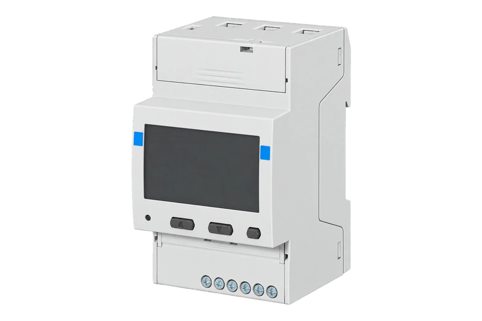
ABB M4M 30 Modbus
Power and energy meter
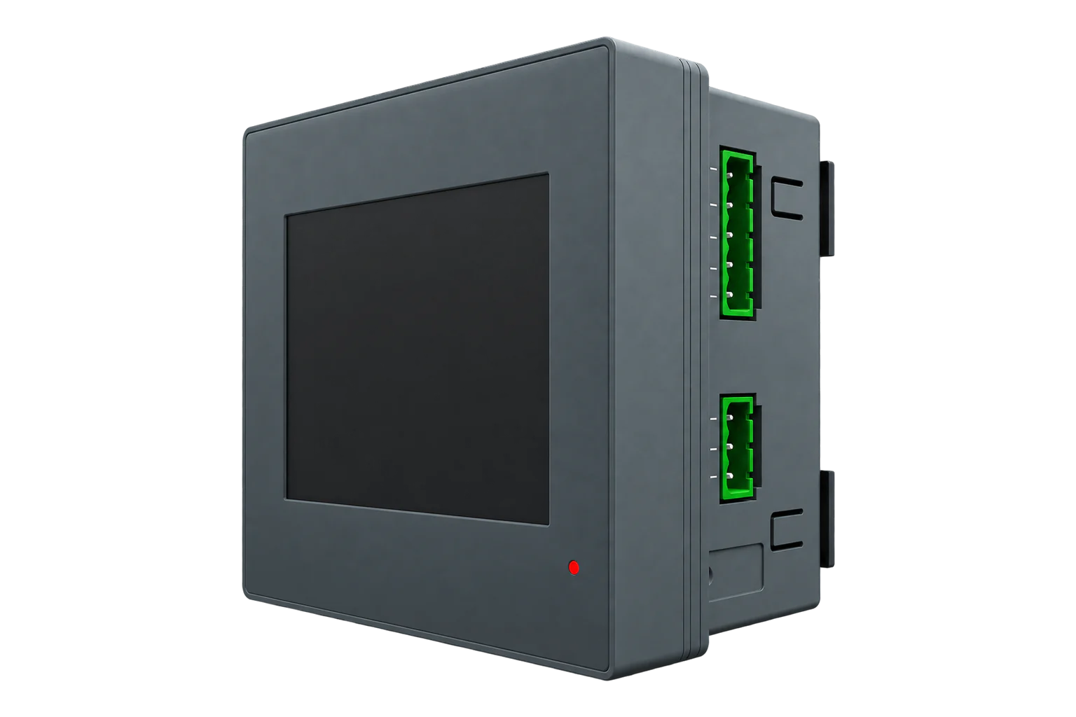
M4M 30 Modbus is a panel network analyser for conventional 1 A or 5 A CTs, with RS-485, Bluetooth commissioning and four programmable I/O. Edge reads its scaled electrical values over Modbus RTU.
- Modbus RTU
Power and energy meter
Compatibility
Compatible through Modbus RTU
ABB documents RS-485 Modbus RTU measurement reads with literal addresses, integer types and scaling.
M4M 30 MODBUS, order code 2CSG274761R4051 (M4M30RS485), using conventional CT inputs. Ethernet, Rogowski, I/O, BACnet, Profibus, MID and M4M32 variants are not interchangeable hardware.
Connect it with
-
Modbus Interface ZMB-3XFrom €399 ex VAT Configure Modbus Interface
-
Gateway ZGW-20From €899 ex VAT Configure Gateway


For M4M30RS485 with a configured slave address
- Modbus
- Wireless
- Edge
- Platforms
Models
| Models | Interface | Route into Edge |
|---|---|---|
| M4M 30 Modbus, 2CSG274761R4051 | Conventional CT inputs; Modbus RTU; four programmable I/O | Use the manufacturer map’s M4M30 product applicability. |
| M4M 30 Ethernet | Separate product with Modbus TCP and Ethernet ports | Use its own network settings; do not infer Ethernet from the family manual. |
| M4M 30 Rogowski / M4M 30-M / M4M32 | Different sensor input, certification or metering specification | Check the exact order code before choosing wiring, accuracy or register scope. |
Specifications
The M4M map is deliberately explicit about engineering units and resolution. A voltage register contains an unsigned integer that must be scaled, whereas other values have different widths and signs. The standard Modbus variant also differs physically from the Ethernet and Rogowski models, even though one user manual covers them together.1
- Order code
- 2CSG274761R4051 / M4M30RS4854
- Current inputs
- Conventional 1 A or 5 A CT secondary; Rogowski is a separate version1
- Communications
- Modbus RTU and Bluetooth; Bluetooth is not the polling path in this guide4
- Serial parameters
- Address 1–247; 9.6, 19.2, 38.4, 57.6 or 115.2 kbit/s; use the configured parity1
- Accuracy
- M4M30 active energy class 0.5S to IEC 62053-22 under the stated measurement conditions1
- Installation envelope
- Front IP54, terminals IP20; operating temperature −25 to +70 °C under manual conditions1
Interface
Documented measurements and integration boundaries for M4M 30 Modbus.
- Phase voltage L1 at 0x5B02: two-register unsigned integer, resolution 0.1 V.
- Phase and line voltages, currents and frequency with their individual workbook resolutions.
- Signed and unsigned power quantities: use the declared data type rather than treating all measurements as FLOAT32.
- Active energy import at 0x5000: four registers, unsigned quantity, 0.01 kWh resolution.
- Demand, alarms and historical records have separate access procedures; historical selection can require writes.
- Meter identity, firmware and configuration to preserve the exact product and scaling context.
- Unavailable unsigned values are FFFF in every register; signed values use their maximum positive code. Keep these as unavailable, not as large real measurements.
Assessment
M4M 30 MODBUS, order code 2CSG274761R4051 (M4M30RS485), using conventional CT inputs. Ethernet, Rogowski, I/O, BACnet, Profibus, MID and M4M32 variants are not interchangeable hardware.
- InteroperabilityWell supported
- Manufacturer protocol manual plus typed, scaled register workbook establish a complete local read path.23
- AccuracySupported with conditions
- Conventional CT inputs and class 0.5S active-energy measurement have defined conditions; CT and wiring error remain separate.1
- SecuritySupported with conditions
- The user manual documents password-controlled configuration; protect the serial segment and omit writes from monitoring.1
- ReliabilitySupported with conditions
- The manual specifies supply, measurement and operating conditions; explicit stale-state handling is still required in the collector.1
- RuggednessSupported with conditions
- IP54 front, IP20 terminals and −25 to +70 °C operating range define a panel-mounted installation envelope.1
Setup
Read and scale L1 phase voltage
ABB’s communications manual gives the FC03 request at 0x5B02, and its mapping workbook defines the two-register unsigned value with 0.1 V resolution.
- Function
- FC03 Read Holding Registers
- Literal PDU address
- 0x5B02 = 23298 decimal; this is already the bus address
- Quantity
- 2 registers, 4 data bytes
- Request PDU
- 03 5B 02 00 02; the RTU client adds the configured slave address and CRC
- Synthetic response data
- 00 00 08 FC, most significant byte first
- Decode
- Unsigned 32-bit 2300 × 0.1 V = 230.0 V
- Acceptance
- Confirm the configured wiring supports L1-N, then compare the scaled value with the simultaneous meter display
Acceptance: The 230 V response is an independently calculated example, not a physical device capture. Never apply the 0.1 multiplier to every register: current, power, energy and status entries have their own type, width and resolution.
-
Match the order code and CT input
Confirm 2CSG274761R4051 and record firmware. This is the conventional-CT Modbus version, not the Rogowski or Ethernet model. Have the authorised installer verify wiring, phase assignment and CT primary/secondary settings.
-
Record the actual serial settings
On the meter, open Configuration, Communication, Modbus RTU. Record address, baud rate and parity and enter those exact values in the Edge connection. Follow ABB’s bus topology and termination instructions and retain one master per segment.
-
Use literal addresses and complete values
ABB’s Start Reg Hex is the address sent on the bus. Convert hex to decimal if the client requires it; do not subtract one. Read both registers of L1 voltage at 0x5B02 in one FC03 request.
-
Decode before expanding the point list
Apply unsigned 32-bit decoding, most significant byte first, and the 0.1 V resolution for the voltage example. Compare the result with the meter display, then configure each further quantity from its own type, register count and resolution.
-
Add current, power and energy
After voltage, add L1 current at 0x5B10 (23312), two unsigned registers × 0.01 A; total active power at 0x5B1A (23322), two signed registers × 0.01 W; and active import/export energy at 0x5000/0x5004 (20480/20484), four unsigned registers each × 0.01 kWh. Use FC03 and high-word-first integer decoding. ABB allows 1–125 registers per read; start with complete values and group nearby points. Reject unavailable raw markers before scaling. Keep configuration, reset and historical-selection writes separate.
Common questions
- Should 0x5B02 become 23297?
- No. ABB states that the hexadecimal start register is expressed exactly as sent on the bus. 0x5B02 is decimal 23298; no one-based correction is applied.2
- Why does a float decoder give nonsense?
- L1 phase voltage is an unsigned integer across two registers, with 0.1 V resolution. Reinterpretation as IEEE-754 FLOAT32 changes the meaning of those bits. Use the workbook’s data type and multiplier.3
- Can I read historical records without any writes?
- The historical interface selects records through header registers and writes before reading data blocks. That is separate from straightforward FC03 live measurements; do not include those selection commands in a read-only polling template.2
Related devices


Sources
- M4M 30/32 user manual, 2CSG445042D0201 (opens in a new tab)
- M4M Modbus communication protocol, 2CSG445050D0201 (opens in a new tab)
- M4M Modbus mapping workbook, 9AKK107492A7627 revision F download (opens in a new tab)
- M4M30RS485 official product record, 2CSG274761R4051 (opens in a new tab)
Further reading
Product names and trademarks belong to their owners. Publication does not imply endorsement or a commercial relationship.